Transcription of III. Synchronous Motors - University of Technology, Iraq
1 SSyynncchhrroonnoouuss MMoottoorrss Dr. SSuuaadd IIbbrraahhiimm SShhaahhll 1 III. Synchronous Motors Synchronous Motors are three-phase AC Motors which run at Synchronous speed, Synchronous Motors have the following characteristics: A three-phase stator similar to that of an induction motor. Medium voltage stators are often used. A wound rotor (rotating field ) which has the same number of poles as the stator, and is supplied by an external source of direct current (DC). Both brush-type and brushless exciters are used to supply the DC field current to the rotor. The rotor current establishes a north/south magnetic pole relationship in the rotor poles enabling the rotor to lock-in-step with the rotating stator flux. Starts as an induction motor.
2 The Synchronous motor rotor also has a squirrel-cage winding, known as an Amortisseur winding, which produces torque for motor starting. Synchronous Motors will run at Synchronous speed in accordance with the formula: Example: the speed of a 24 -Pole Synchronous Motor operating at 60 Hz would be: 120 x 60 / 24 = 7200 / 24 = 300 RPM Synchronous Motor Operation The squirrel-cage Amortisseur winding in the rotor produces Starting Torque and Accelerating Torque to bring the Synchronous motor up to speed. When the motor speed reaches approximately 97% of nameplate RPM, the DC field current is applied to the rotor producing Pull-in Torque and the rotor will pull-in -step and synchronize with the rotating flux field in the stator. The motor will run at Synchronous speed and produce Synchronous Torque.
3 SSyynncchhrroonnoouuss MMoottoorrss Dr. SSuuaadd IIbbrraahhiimm SShhaahhll 2 After synchronization, the Pull-out Torque cannot be exceeded or the motor will pull out-of-step. Occasionally, if the overload is momentary, the motor will slip-a-pole and resynchronize. Pull-out protection must be provided otherwise the motor will run as an induction motor drawing high current with the possibility of severe motor damage. Characteristics and Features The rotation of a Synchronous motor is established by the phase sequence of the three-phase AC applied to the motor stator. As with a three-phase induction motor, Synchronous motor rotation is changed by reversing any two stator leads. Rotor polarity has no effect on rotation. Synchronous Motors are often direct-coupled to the load and may share a common shaft and bearings with the load.
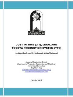
4 Large Synchronous Motors are usually started acrossthe- line. Occasionally, reduced voltage starting methods, such as autotransformer or part-winding starting, may be employed. SSyynncchhrroonnoouuss MMoottoorrss Dr. SSuuaadd IIbbrraahhiimm SShhaahhll 3 Equivalent Circuit and Phasor Diagram of a Synchronous Motor The steady-state performance characteristics of the Synchronous motor may be studied using the equivalent circuit shown in Fig. 2. Comparing this with Fig. 1, it should be noted that the direction of armature current Ia has been reversed. Figure 1: Synchronous generator Equivalent circuit and phasor diagram of a Synchronous generator per phase SSyynncchhrroonnoouuss MMoottoorrss Dr.
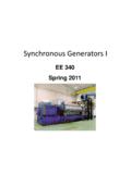
5 SSuuaadd IIbbrraahhiimm SShhaahhll 4 Equivalent circuit and phasor diagram of a Synchronous motor per phase Figure 2: Synchronous motor The circuit equation for a Synchronous motor is thus = + + = This is exactly the same as the equation for a generator, except that the sign on the current term has been reversed. In order to satisfy the above circuit equation, the phasor R (often regarded as the back emf of the motor) must lag the terminal voltage by the load angle . Example: A 1492 kW ,unity power factor,3-phase ,star-connected ,2300 V, 50 Hz, Synchronous motor has a Synchronous reactance of ohm/phase.
6 Compute the max. torque in N-m which this motor can deliver if it is supplied from a constant frequency source and if the field excitation is constant at the value which would result in unity power factor at rated load. Assume that the motor is of cylindrical rotor type. Neglect all losses. Solution: Rated kVA, 3-phase= S = 1492 Rated kVA per phase = 14923= Rated Voltage/phase = V =2300 3= SSyynncchhrroonnoouuss MMoottoorrss Dr. SSuuaadd IIbbrraahhiimm SShhaahhll 5 Rated current , I = 1000 = Phasor diagram: = 2+( )2= = = / =2 =2 50=.
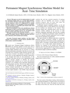
7 , = = / 3 . =9855 Effect of field Excitation: V-curves Assume that a Synchronous motor is driving a constant torque load. The active power converted by the machine is constant, since the power, the voltage and the motor speed are constant. Thus, SSyynncchhrroonnoouuss MMoottoorrss Dr. SSuuaadd IIbbrraahhiimm SShhaahhll 6 Figure 3 shows the effect of change in field excitation on the operation of the Synchronous motor. As the field current is changed, the tip of armature current phasor I will follow the locus XX (a line perpendicular to V), while the tip of the back emf phasor Ef will follow the locus YY (a line perpendicular to , where I2 Suppose the Synchronous motor is initially overexcited (in other words, excited with a large field current ) and is operating at point 1, as shown in Figure 3.)
8 The corresponding armature current Iis the in-phase component of armature current ). 1 is leading V, and hence the input power factor is leading. Reduction of field current causes the tip of Ef phasor to move towards SSyynncchhrroonnoouuss MMoottoorrss Dr. SSuuaadd IIbbrraahhiimm SShhaahhll 7 point 2: the armature current decreases to a minimum (I2) and the motor input power factor increases to unity. Further reduction of field current causes Ef to move to point 3: The armature current increases to I3 and the input power factor becomes lagging. Figure 3: Effect of field excitation on performance of a Synchronous motor XX locus of armature current at constant power; YY locus of open-circuit voltage at constant power.
9 When the Synchronous motor operates with constant power input, the variation of armature current with field current is thus a V-shaped curve, as illustrated in Figure 4. In general, overexcitation will cause the Synchronous motor to operate at a leading power factor, while underexcitation will cause the motor to operate at a lagging power factor. The Synchronous motor thus possesses a variable-power-factor characteristic. Figure 4: Synchronous motor V-curves SSyynncchhrroonnoouuss MMoottoorrss Dr. SSuuaadd IIbbrraahhiimm SShhaahhll 8 Example: A factory takes 600 kVA at a lagging power factor of A Synchronous motor is to be installed to raise the power factor to lagging when the motor is taking 200 kW.
10 Calculate the corresponding apparent power (in kVA) taken by the motor and the power factor at which it operates. Solution: Load power factor, Cos = Sin = Load kVA = 600 P1, Load power = load kVA*cos = 360 kW Q1, Load reactive power = kVA*Sin = 480 kVAr P2, Motor power = 200 kW Overall , Cos = lag tan = Since, tan =( 1 2) 1+ 2 , 2= 1 ( 1+ 2)tan = S2, Apparent power of the motor = 22+ 22= Motor =P2/S2= lead Applications of Synchronous Motors Synchronous Motors are used for constant speed, steady loads. High power factor operations these Motors are sometimes exclusively used for power factor improvement. These Motors find application in driving low speed compressors, slow speed fans, pumps, ball mills, metal rolling mills and process industries.