Transcription of Impedance Matching Transformers for Receiving Antennas …
1 1 Impedance Matching Transformers for Receiving Antennas at Medium and Lower Shortwave Frequencies June /July 2003 Bill Bowers John bryant Nick Hall-Patch, VE7 DXR INTRODUCTION by John bryant All three of the co-authors have been involved in designing, fabricating and testing Impedance Transformers for many years. In fact, I first met Nick Hall-Patch when I asked his assistance in designing a Matching transformer soon after erecting my first Beverage antenna in 1985. Nick, then as now, the Technical Editor of the International Radio Club bulletin, had written and/or edited some of the early articles on this subject. Subsequently, Nick and I co-authored several articles on Impedance Matching devices and associated subjects throughout the 1990s.
2 The most recent such article "Fabricating Impedance Transformers for Receiving Antennas " was written by me in May of 2001 and published in numerous club bulletins and on the Internet. Nick and Bill were unattributed advisors on that article. With each of those articles, we were intensely aware that we were relying on conventional wisdom and the general state of the art at the time of authoring. We were also aware that there were some assumptions inherent in the basic formula governing the design of Impedance Transformers that we had not seen tested. At the time, the only source for technical data and design formula were in the professional realm and from manufacturers of ferrite toroids. In early 2003, DXer George Maroti, mentioned to Nick that although he had been very successful in following the article guidelines for Impedance Matching Transformers with isolated windings, he had noticed that ferrite core types 43, 73 and 75 had all been suggested for use in these Transformers by different people.
3 He inquired what parameter(s) are critical in determining what material to use for a given frequency range? and Nick had to admit that, other than the following the recommendations offered by the core manufacturers, he did not have a clear answer to that question. Happily, our total reliance on standard formula and data had begun to change as Bill Bowers became more active as a radio enthusiast. Bill, educated in physics and electrical engineering, spent his career focused on the transmission of low-level signals and the magnetic properties of the electro-mechanical cables used in logging oil wells..In recent years, Bill has been heavily involved in developing circuits and Antennas for the Lowfer hobby (150 to 300 kHz.) and has slowly built his array of sophisticated test instruments to the level that many professional labs would look at with envy.
4 About two years ago, Bill began a cycle of design and testing that would lead to a series of articles on Impedance Transformers for Receiving Antennas at low frequencies. This work led to some basic changes in the design formula for Impedance Transformers , at low frequencies. Bill and I had worked together in testing Antennas in years past. When he learned of our interest in investigating the design of Impedance Transformers for signals on medium wave and "Tropical Band" frequencies, Bill was very interested in participating. Fortunately, these frequencies - from about 300kHz to 5 MHz - cover some of the most popular frequency ranges of radio amateur operation, as well. It took no persuasion at all to have Nick join the team as an essential advisor to Bill.
5 Beside having been Technical Editor for IRCA for many years, Nick is also an electronics professional, being involved in the design, fabrication and operation of electronic instrumentation used primarily in oceanography. Throughout the study, Nick worked with Bill on some of the finer technical points of transformer design while I took notes and acted as cheerleader and scribe. The three authors wish to extend special thanks to Guy Atkins and Mika Makelainen. Guy worked his usual professional-level graphics wizardry to reduce the file size of this article from over 4 megabytes to its current svelte size. We would also like to thank Mika for being willing to publish such an extensive article on this subject. That is, we hope, a real service to several of the radio-related communities.
6 Despite the fact that our previous articles on this subject were based on the state-of-the-art at the time, Nick and I are surprised that this study shows that the state-of-the-art and "conventional wisdom" was far from the best. I will be rebuilding all of my Transformers based on the findings of this study; I suspect that Nick and probably you will be doing some rebuilding, too. 2 Impedance Before discussing the design of Impedance Transformers , it is useful to briefly discuss the nature of Impedance and Impedance in Receiving Antennas , since many radio enthusiasts find the concept somewhat slippery. Impedance is a force that inhibits the flow of alternating current through a transmission line, transformer, coil, etc. When dealing with DC current flow, the only inhibition to current flow is simple resistance, measured in ohms.
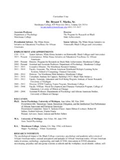
7 With alternating current, two other inhibiting effects come into play: inductive reactance and capacitive reactance. These are each generated by the fact that the current is alternating and by the physical attributes of the device or conductor in question. The summation of all three of these inhibitions to AC current flow is Impedance , also measured in ohms. FIGURE 1 Why is all of this important? It is absolutely provable that the maximum signal power transfers from the antenna to the receiver when the resistive component of the antenna is equal to the resistive component of the receiver and the reactive component of the antenna and receiver are equal but opposite in sign. That is the ideal condition and the goal to which all antenna- Matching devices aspire.
8 Most modern communications receivers are designed for the 50-ohm Impedance available from common RG-8 or RG-58 coaxial cable: theoretically, a perfect match. If 50-ohm coaxial cable is used to bring signals to a 50-ohm receiver, the primary Impedance concern remaining is achieving a good Impedance match between the antenna and the coaxial cable. That, of course, is the purpose of this study. Although our work concentrated exclusively of the Impedance device itself, it is important to remember that Impedance of the Antennas that we are attempting to match is a moving target. Impedance in Antennas is dependant on their length, height above ground, configuration and often, on the frequency of the signals being received. Most Beverage Antennas are said to have a characteristic Impedance of about 450 ohms.
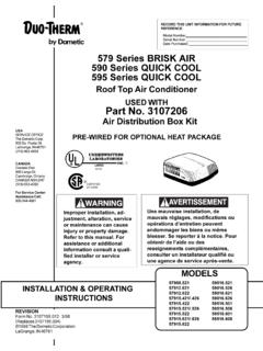
9 For a cardioid (one direction) reception pattern, it is further recommended that the far end of the antenna be grounded through 450 ohms of non-inductive resistance. Figure 2 is from our 1989 article that illustrates the variation in Impedance at various frequencies found by John in the 1200 foot "Okie" Beverage. Unfortunately, our instrumentation at the time only tuned down to 1 MHz. Note also how much more consistent the Impedance becomes when the antenna is properly terminated at the far end. This is a real argument for always terminating Beverages unless reception off the backside is really desirable. Given the widely varying (with frequency) Impedance of Beverage and similar Receiving Antennas , we felt that it was most reasonable to attempt to maximize the efficiency of the Impedance transformer about the approximate characteristic Impedance of Beverages (450 ohms) and to also develop a design at 900 ohms to work with Deltas, Flags, Pennants, etc.
10 3 FIGURE 2 DESIGN CONSIDERATIONS Initially, our general design goals were to determine the most appropriate ferrite type, winding pattern and turns count for several frequency bands within the 150 kHz. to 7 MHz range. We expected to recommend one design if you were for MW+LW, maybe a second for MW only and a third design for MW+ lower SW. We did not imagine that there would be a single design that would work fairly well at LF, and excellently at least up to 5 MHz, with some service above that, though this would be our ideal, since many Listener DXers are somewhat interested in DXing the few remaining LW broadcasting stations and are intensely interested in DXing either the MW band or the so-called Tropical Bands (up to about MHz.)