Transcription of In-Line Air Separators - TACO - HVAC
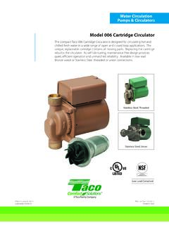
1 Effective Date: 04/09/13 Printed in USAAir Elimination & control Taco Catalog # Supersedes: 04/01/86 The AC models of air Separators deliver all the quality and performance you expect from Taco products. They are built to last with shell, heads and ANSI flanges with ASME constructed for 125, 150, 250 and 300psi working pressures all while providing outstanding performance in the field, up to a maximum operating temperature of 375 F. The AC product line is available in standard sizes from 2 through 20 to meet the needs of a broad range of applications with custom unit sizes available up to 36 pipe Air SeparatorsFeatures & Benefits2 Air trapped in the system can produce major problems such as reduced heat transfer, loss of system efficiency, pipe corro-sion, pump damage, increased energy consumption and irritating noise.
2 The highly efficient Taco air separator clears the system of free air and reduces un-dissolved sediment to save money, energy and component wear. Unlike many competitive models each unit is designed, constructed and tested to the requirements of Section VIII, Division I of the ASME pressure vessel code as for use in hydronic heating or cooling systems, Taco s compact, highly efficient air separator provides air separation while minimizing space requirements. Taco offers these Separators with or without strainers, in standard pipe line sizes from 2 to 20 with custom unit sizes up to 36 pipe size. The wide range of sepa-rator models have been developed for applications with flowrates up to 12,500 gpm.
3 This wide range of models allows optimum selections with reduced pressure drop requirements. The standard product is designed for working pressures of 125 psi at 375 F. Optional 150, 250 and 300 psi maximum pressure units, 375 F maximum temperature units are also available. Taco air Separators are manufactured from carbon steel listed in ASME Section II. Consult the factory for higher working pressures, larger sizes or non-standard materials of SEPARATORCOLD WATERMAKE-UPINSTALL TEETACOPRESSUREREDUCINGVALVETACO 409 AIR VENTR ecommended/Typical InstallationAir separator Flow PatternVent connection allows captured air to be vented to atmosphere (Air Elimination System) or directed to a plain steel expansion tank (Air control System).
4 INLETW ater & airmixturethroughthe inlet.* Provided as standard on F model unitsOptional 304 Stainless steel strainer* 3/16 and larger debris captured with forces change in flow direction and slows the velocity, releasing the air through the to piping ASME Air Separators (AC)Taco In-Line Air Separators are applied in commercial, institutional and industrial applications for the removal of free air in water or water/glycol systems. The In-Line designed air separator utilizes the advantages resulting from large body diameter in relation to the entering nozzle design of In-Line air Separators depends upon the lowering of the system fluid velocity within the separator , the change in direction of fluid flow within the unit, and buoyant force direct air to the automatic air vent normally positioned at the top of the air Separators are designed, built and stamped to the requirements of ASME.
5 The rated working pressure of these units is dependent upon the design pressure of the hydronic system into which they are being installed. Manufacturers offer these unit working pressures of 125, 150, 250 and 300 psi and higher if required. Optional stainless steel strainers are specified to capture and allow the removal of larger debris. (3/16 and larger) These screens are normally specified with 3/16 inch perforations and free area of not less than 5 times the open area of the nozzle to minimize pressure drop. Most manufacturers provide a blowdown connection at the bottom of the In-Line Air Separators are installed in con-ventional Air control Systems with plain steel expansion tanks (Figure A) care must be taken to insure that piping between the air separator and the plain steel expansion tank is pitched at least 3 degrees to facilitate the migration of captured air back into the expansion vessel.
6 Systems with plain steel expansion tanks must not have automatic vents installed as this will lead to the loss of the expansion tank compression : FIGURE #3 LOCATION: STRAINER REMOVALCOLD WATERSUPPLYTACO CAPTIVE AI REXPANSION TANKTACO PRESSUREREDUCING VALVETACOAI R SEPERATORPRESSURE GAUGETACO PUMPTACO SUCTION DIFFUSERTACO MULTI-PURPOSEVALVETACO HY-VENT GATE VALVEUNIONDRAINCOCKF igure BNAME: FIGURE #3 LOCATION: STRAINER REMOVALCOLD WATERSUPPLYTACO PLAI N STEELEXPANSION TANKTACO PRESSUREREDUCING VALVETACOAI R SEPERATORSLOPE PIPEUP TO TANKPRESSURE GAUGETACO PUMPTACO SUCTION DIFFUSERTACO MULTI-PURPOSEVALVEGATEVALVEF igure AAir separator with Plain Steel Expansion TankAir separator with Captive Air TankWhen In-Line Air Separators are installed in Air Elimination Systems (Figure B) with Captive Air bladder or diaphragm style expansion tanks, automatic air vents should be installed at the top of each separator .
7 As Air Elimination systems have a permanent separation provided by the bladder of diaphragm between the initial tank pre-charge and the system fluid no loss of pre-charge air will occur. Applications Larger systems Lower pressure drop Removal of larger particles ApplicationsAir control and EliminationWater contains a certain amount of entrained air. If this air comes out of solution, it can increase corrosion rates of metals within the system. In addition, air can form pockets at the top of pipes and heating units. These air pockets can actually restrict or block flow in a hydronic piping system. This is referred to as air locking .The table below shows a solubility curve for air in water.
8 Note that at a fixed pressure, increasing the temperature reduces the amount of air that can be dissolved. For example, at 60 PSIA and 40 F, the water can contain just over 10% air by volume. At 60 PSIA and 200 F, the percentage decreases to just over 4%.Conversely, at fixed temperature reducing the pressure reduces the amount of air that can be dissolved. For example at 100 F and 80 PSIA the water can contain 8% air by volume. At 100 F and 20 PSIA the percentage decreases to 2%.90807060504030201018%16%14%12%10%8%6% 4%2%325075100 TEMPERATURE (DEGREE F)SOLUBILITY OF AIRIN WATER AT STANDARDTEMPERATURE AND PRESSURE125150175200212 PSIAS olubility CurveFigure 1 The conclusion is that air is least soluble in water at the highest temperature and lowest pressure.
9 Air Separators should therefore be located at these highest temperature in a system is typically on the discharge of boilers and inlet of chillers. Therefore, the general rule of thumb in hydronic systems is that Air Separators should be located downstream of boilers (Figure 2) and upstream of chillers (Figure 3). The lowest pressure in a system is typically at the expansion tank, since this is the point of no pressure change and the location of the fill valve. Therefore, the general rule of thumb in hydronic systems is that Air Separators should be located at the expansion tank connection to the system. FAN COILTACOCIRCULATORTACO TWIN TEETACO AI R SEPARATORBOILERTACOEXPANSIONTANKTACO MULTI-PURPOSEVALVETACO PUMPTACO SUCTION DIFFUSERGATE VALVEUNIONDRAINCOCKB oiler and air separator LocationFigure 2 NAME: FIGURE 8 LOCATION: FAN COILTACOCIRCULATORTACOTWIN TEETACO AI R SEPARATORCHILLERTACOEXPANSIONTANKTACOMUL TI-PURPOSEVALVETACO PUMPTACO SUCTION DIFFUSERGATE VALVEUNIONDRAINCOCKC hiller and air separator LocationFigure 3 Applications5In addition, as water is heated from the fill tempera-ture to the operating temperature, a great deal of air is released.
10 Therefore, the simple act of bringing the water to operating temperature could lead to corrosion and air pockets, both of which should be method of removing this released air from the pip-ing system is therefore required. Enter the air separa-tor. An air separator is a device that is removes the air from the circulating fluid. There are several types of air Separators in use today. Depending upon the type of expansion tank used in the system, the air separator is part of an Air control System or an Air Elimination control SystemsIf a conventional (non-bladder) style expansion tank is used, it is desirable to redirect the separated air to the space above the water level in the expansion tank (Figure 4).