Transcription of IN series - ITUR
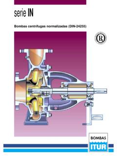
1 IN seriesCentrifugal pumps standardized to DIN-242552 The new standardized IN series are single-stage horizon-tal centrifugal pumps, with axial suction and radial dis-charge, buit to Standard DIN-24255, and evolved as a resultof the latest hydraulic and technological innovations applied tothe design and manufacture of the well-proven and well-known Norma series of ITUR Pumps. Evolved in order tocover a wide variety of pumping requirements, they offer solu-tions and improvements with:- High efficiency,- Sturdy design- Variety of materials, according to the liquid being Sealed by mecanical seal or Amply-dimensioned Standardized parts with high degree of intechangeability- Minimal and rapid these pumps are normally driven by an electricmotor, other power-drive sources may be used (diesel motor,steam turbine, hydraulic motor.)
2 The IN- series of ITUR Pumpshas been specially conceivedfor the pumping of liquids, generally clean or lightly contami-nated. The field of application of the series extends to all thepumping needs for the requirements of medium-duty services:OMunicipal or industrial water supplyOWater and oil channelling systemsOSupply of hot water to large buildingsOClimatization installationsOConstant-pressure water equipmentOFire-protection equipmentOIrrigationThe IN- series , standardized to DIN-24 255 comprises a totalof 47 different models, based on 34 pump sizes, where eachsize allows for one or two types of impeller (A or B).Service limits- Maximum flow: ..600 m3/h- Maximum height differential ..105 Maximum casing pressure (at 20 C) ..10 Maximum suction pressure ..5 Kg/ Maximum speed .. rpm- Maximum temperature.
3 140 C- Maximum viscosity ..20 cSt (2,9 E) With consultation, some of the standard construction limits laid down canbe exceeded. There are 13 larger models for flows of up to 1600 m3/h.(See catalogue for IN series - complementary sizes).The standard version of the electro-pump unit embodies thenormal semi-flexible coupling. Upon request, this coupling canbe supplied with a spacer. The use of the semi-flexible cou-pling with a spacer allows easy access to the pump interiorwithout the need to remove the pipes or the removing the spacer, the assembly made up of the sup-port, cover and impeller is removed, the pump casing and themotor always remaining attached to the bed-plate. The suctionand discharges pipes remain this way the maintenance tasks are made easier, especial-ly when dealing with a fixed installation with several CasingWith volute casing and support feet, it embodies the flangesfor the suction (axial) and discharge (radial upwards), andincorporates a wear ring.
4 The casing-to-cover sealing iseffected by means of an embedded and discharge flangesIntegrally cast with the casing constructed to DIN-2501 crack-le-finished RF to DIN-2526 form C. Valid for connecting tocommercial flanges DIN PN10. DESCRIPTION APPLICATIONS EASE OF MAINTENANCE PUMP DENOMINATION RANGE OF THE SERIESIN SeriesDN of discharge outlet, in mmNominal diameter of impeller, in mmImpeller typeIN-100/250 B CONSTRUCTIONA uxiliary connectionsThe standard version comes with two connections: one forvent/primming or pressure gauge and other for drain purposes, bothdrilled and closed off with the corresponding coverCast in one piece, of integral design, with the seal or the packing. Itincorporates the rear wear ring. It allows for connections for the sealcirculation by the liquid being pumped: plans API-01 (internal).
5 Wear ringsAll models incorporate a forward wear ringin the casing and a rearwear ringin the cover, in order to avoid expensive repairs and toreduce their costs, through the natural loss of adjustment producedthrough time with the efficiency closed impeller, cast in one piece, hydraulically anddynamically balanced. Hydraulically relieved by means of the axialthrust compensation drill holes, it is keyed to the shaft andlocked by means of two shaftWell-dimensioned, the shaft is especially resistant to bending. It isprovided with a replaceable sleeve, sealed with the shaft itself bymeans of a O ring. Thus, changing the shaft can be avoided, in thecase of wear or abrasion in the sealing or packing area, in this wayachieving quick and cheap supportOf modern design, it incorporates two ball bearings, situated atboth ends of the support.
6 Some pump sizes carry adouble raw ballbearingon the pump side. It has a protective deflectoragainst theingress of bearings have been calculated to give a minimum lifespan hours, although most model exceed hours. They aregrease-lubricated, the support incorporating greasersin its sealing systemsBy means of mechanical seal or packing. The standard versionembodies the API-01 plan of internal circulation. Simple mechanical DIN sealStandardized to DIN-24960. The material used in the contactingfaces and in the joints depends upon the liquid to be , provided with the corresponding of the mechanical seal with plan API-01 (internal)Packing detail with plan API-01 (internal).4 The IN series of ITUR Pumpshas been studied in 6 differentversions of the highest quality Standardized aim of standardizing the materials is to seek Standardizedsolutions for the entire range of pumps in medium-duty ser-vice, in order to provide a fast, flexible Service for the normaldemand for this type of , if the type of service for which the pumps aredestined requires it, upon request they can be manufactured inother classes of such a case, consult the ITUR PumpsEngineeringDepartment, who will study and offer the most favourable solu-tion in each particular case.
7 STANDARDIZED MATERIALSThe Table below shows the seal diameters, and the size andnumber of packing rings corresponding to the IN Seriesofpumps, in the sizes standardized to DIN-24255. The data iscross-referenced to the interchangeability Table on the follow-ing page, for pumps constructed of standardized materials andstandard : Pump IN-65/125B has a seal diameter (Group B onthe Interchangeability Table) of 28 mm, or in thecase of packing (Group A on the InterchangeabilityTable) incorporates 4 packing rings with eachsquare-sectioned of 8 following Table shows the maximum rotational speed foreach size pump. These values have been calculated for nor-mal, continuous, pump operation, pumping clean water at20 C, with a specific weight of 1 special cases, such as emergency pumps or others, withconsultation these limits can be DATA(P) = Version with packing(S)= Version with mechanical seal(1) = The shaft is made of F-127 BO ( ) for 80/135 sizes at more than 1800 rpm, and 100/315 at more than 1500 rpm, up to 2200 rpm.
8 (2) = CF8M. Terminology for cast-in VERSION500-GG-25501-MIXTA502-MISTINOX 503-BRONCE of partMaterialNr. DIN MaterialNr. DIN MaterialNr. DIN MaterialNr. DIN MaterialNr. DIN MaterialNr. DIN102 Pump shaftF-114(1) (1) (1) (1) 10 AISI-316(2) 10 G-CuSn 10 box (P) Casing wear Cover wear sleeve (S) sleeve (P)AISI-431 Impeller Driving sealdiameterSize of thepackingsquare-sectionedPackingringsnu mberGroup of the interchangeability standardization of parts and materials of the IN-Seriesmakespossible a high number of common and interchangeable partsbetween the different pump standardization infers an operational saving in costs, since itminimises the stock of parts required to guarantee the efficient main-tenance of many different models of components listed in the upper part of the table are standard andinterchangeable between the different types of pumps, provided thatthe same letter and colour are shown in the cross-reference pump shaft of model IN-32/125A is identical and inter-changeable, at the same material, with that of models.
9 IN-32/125B IN-40/125B IN-32/160A IN-32/160 BSince in the column pump shaft the letter Aappears in all of PARTS ITUR Pumps practices a policy of continual development of its models. For this reason specifications are subject to change without OFPUMPIN-Title of part and reference number in the pump explosed y y 524 Pumpshaft210 Simple mechanical seal versionPacking versionMcch. scal433 Spacer504 Pump cover161 Facking461 Lantern458 Stutfing-box452 Pump cover16132/125 AAAAAAAAAACM-1 AAAE-132/125 BAAAAAAAAACM-1 AAAE-140/125 BAAAAAAAAACM-1 AAAE-132/160 AAAAAAAAAACM-2 AAAE-232/160 BAAAAAAAAACM-2 AAAE-250/125 BAAABBBBBBCM-3 ABBE-365/125 BAAABBBBBBCM-3 ABBE-340/160 AAAABBBBBBCM-4 ABBE-440/160 BAAABBBBBBCM-4 ABBE-450/160 AAAABBBBBBCM-4 ABBE-450/160 BAAABBBBBBCM-4 ABBE-465/160 BAAABBBBBBCM-5 ABBE-580/160 BAAABBBBBBCM-5 ABBE-532/200 AAAABBBBBBCM-6 ABBE-632/200 BAAABBBBBBCM-6 ABBE-640/200 AAAABBBBBBCM-6 ABBE-640/200 BAAABBBBBBCM-6 ABBE-650/200 AAAABBBBBBCM-7 ABBE-750/200 BAAABBBBBBCM-7 ABBE-765/200 AAAABBBBBBCM-7 ABBE-765/200 BAAABBBBBBCM-7 ABBE-732/250 BAAABBBBBBCM-8 ABBE-840/250 AAAABBBBBBCM-9 ABBE-940/250 BAAABBBBBBCM-9 ABBE-950/250 AAAABBBBBBCM-9 ABBE-950/250 BAAABBBBBBCM-9
10 ABBE-980/200 BBBBCCCCCCCM-10 BCCE-10100/200 ABBBCCCCCCCM-10 BCCE-10100/200 BBBBCCCCCCCM-10 BCCE-1065/250 BBBBCCCCCCCM-11 BCCE-1180/250 ABBBCCCCCCCM-11 BCCE-1180/250 BBBBCCCCCCCM-11 BCCE-11100/250 BBBBCCCCCCCM-12 BCCE-12125/250 ABBBCCCCCCCM-12 BCCE-12125/250 BBBBCCCCCCCM-12 BCCE-12150/200 BBBBCCCDCCCM-13 BCCE-13150/250 BBBBCCCDCCCM-14 BCCE-1440/315 BBBBCCCDCCCM-15 BCCE-1550/315 BBBBCCCDCCCM-15 BCCE-1565/315 BBBBCCCDCCCM-16 BCCE-1680/315 BBBBCCCDCCCM-17 BCCE-17100/315 BBBBCCCDCCCM-17 BCCE-17125/315 BCDDDDDEDCCM-18 BDDE-18150/315 BCDDDDDEDCCM-18 BDDE-18100/400 BCDDDDDEDCCM-19 BDDE-19125/400 BCDDDDDEDCCM-20 BDDE-20150/400 BCDDDDDEDCCM-20 BDDE-206 These diagrams make possible a rapid selection of the most suitable type of pump. These are occasions in which, once apump has been selected, it will also be possible to find another which may satisfy the task conditions with greater efficiencyor less NPSH required.