Transcription of Inductive proximity sensors - Nexiot
1 2/102 General2 Inductive proximity sensors2 RecommendationsThe sensors detailed in this catalogue are designed for use in standard industrial applications relating to presence sensors do not incorporate the required redundant electrical circuit enabling their usage in safety safety applications, please refer to our Safety solutions using Preventa and certifications Parameters related to the environmentQuality controlOur Inductive proximity sensors are subject to special precautions in order to guarantee their reliability in the most arduous industrial vThe product characteristics stated in this catalogue are subject to a qualification procedure carried out in our particular, the products are subjected to climatic cycle tests for 3000 hours whilst powered-up to verify their ability to maintain their characteristics over time. bProductionvThe electrical characteristics and sensing distances at both ambient temperature and extreme temperatures are 100% are randomly selected during the course of production and subjected to monitoring tests relating to all their qualified returnsIf, in spite of all these precautions, defective products are returned to us, they are subject to systematic analysis and corrective actions are implemented to eliminate the risks of the fault to standardsAll Telemecanique brand Inductive proximity sensors conform to and are tested in accordance with the recommendations of standard IEC shock resistanceThe sensors are tested in accordance with standard IEC 60068-2-27, 50 gn, duration 11 resistanceThe sensors are tested in accordance with standard IEC 60068-2-6, amplitude 2 mm, f = Hz, 25 gn at 55 to the environmentbPlease refer to the characteristics pages for the various 67: protection against the effects of immersion.
2 Test conforming to IEC 60529: sensor immersed for 30 minutes in 1 m of deterioration in either operating or insulation characteristics is 68: protection against prolonged immersion. sensor immersed for 336 hours in 40 metres of water at 50 deterioration in either operating or insulation characteristics is sensors with an IP 68 degree of protection are ideal for use in the most arduous conditions, such as machine tools, automatic car to electromagnetic interferencebElectrostatic dischargesa and z versions: level 4 immunity (15 kV). IEC 61000-4-2bRadiated electromagnetic fields (electromagnetic waves)c, a and z versions: level 2 (3 V/m) or level 3 (10 V/m) immunity. IEC 61000-4-3bFast transients (motor start/stop interference)c version: level 3 immunity (1 kV).a and z versions: level 4 immunity (2 kV) except 8 mm model (level 2). IEC 61000-4-4bImpulse voltagec, a and z versions: level 3 immunity ( kV) except 8 mm and smaller models (level 1 kV).
3 IEC 60947-5-2 Resistance to chemicals in the environmentbOwing to the very wide range of chemicals encountered in industry, it is very difficult to give general guidelines common to all sensors . bTo ensure lasting efficient operation, it is essential that any chemicals coming into contact with the sensors will not affect their casing and, in doing so, prevent their reliable and flat plastic case sensors offer excellent overall resistance to: vchemical products such as salts, aliphatic and aromatic oils, petroleum, acids and diluted bases. For alcohols, ketones and phenols, preliminary tests should be made relating to the nature and concentration of the and beverage industry products such as animal or vegetable based products (vegetable oils, animal fat, fruit juice, dairy proteins, etc.).In all cases, the materials selected (see product characteristics) provide satisfactory compatibility in most industrial environments (for further information, please consult your Regional Sales Office).
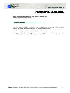
4 InsulationClass 2 devices iElectrical insulation conforming to standards IEC 61140 and NF C 20-030 relating to means of protection against electric 25 C%Temperature CHumidity as %- 25 + 70 C cycle, 95% RHTemperatureRelative humidity2/112 General2 Inductive proximity sensors2 Principle of Inductive detectionOperating principle1 Oscillator2 Output driver3 Output stagebAn Inductive proximity sensor is solely for the detection of metal basically comprises an oscillator whose windings constitute the sensing alternating magnetic field is generated in front of these of an Inductive proximity sensorDetection of a metal object bWhen a metal object is placed within the magnetic field generated by the sensor , the resulting currents induced form an additional load and the oscillations causes the output driver to operate and, depending on the sensor type, a normally open (NO) or normally closed (NC) output signal is proximity detectionbInductive proximity sensors enable the detection, without physical contact, of metal objects.
5 BTheir range of applications is very extensive and includes: vmonitoring the position of machine parts (cams, end stops, etc.),vcounting the presence of metal objects, of Inductive detectionbNo physical contact with the object to be detected, thus avoiding wear and enabling detection of fragile objects, freshly painted objects, operating rates. Fast resistance to industrial environments (robust products, fully encapsulated in resin).bSolid-state technology: no moving parts, therefore service life of sensor not related to number of operating sensors are suitable for all metal environments (flush mountable or non flush mountable) since they ensure a maximum sensing distance, even if there is a metal background. Precise detection of the position of the object can be obtained using the teach mode. For further information, see pages 2/20 and 2 indicatorOutput LEDAll Telemecanique brand Inductive proximity sensors incorporate an output state LED sensors are fitted with a green LED that indicates Power on and also assists the user during setting-up (teach mode).
6 Mounting sensors on a metal supportSensors suitable for flush mounting in metalbNo side clearance models using the Osiconcept system are flush mountable in metal without reducing the sensing distance and also enable the detection of an object against a metal background. For further information, see pages 2/20 and 2 not suitable for flush mounting in metalbSide clearance distance greater than that for a standard flush mountable Osiconcept system eliminates the side clearance requirement. For further information, see pages 2/20 and 2 object presentNO outputNC output3 SnObject to be detectedMetalMetal3 Sn2 SnObject to be detectedMetalMetal2/122 General2 Inductive proximity sensors2 Mounting sensors on a metal supportMounting using fixing clampbStandard flush mountable models: e = 0, h = 0bStandard non flush mountable models:v / 8 / 12 mm: e = 0, h = 0,v 18 mm: if h = 0, e u 5; e = 0, h u 3, 30 mm: if h = 0, e u 8; e = 0, h u models: e = 0, h = 0 Mounting distance between sensorsStandard sensorsIf 2 standard sensors are mounted too close to each other they are likely to lock in the detection state due to interference between their respective oscillating avoid this condition, minimum mounting distances stated for the sensors should be adhered to or, alternatively, sensors with staggered oscillating frequencies should be frequency sensorsFor applications where the minimum recommended mounting distances for standard sensors cannot be achieved, it is possible to overcome this restraint by using staggered frequency sensors .
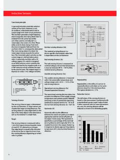
7 Please consult your Regional Sales this case, a staggered frequency sensor is mounted adjacent to or opposite each standard torque for cylindrical type sensorsMaximum tightening torque for the various sensor case materialsBrassBrassStainless steelPlasticDiameter of sensor (mm)Short case modelForm A modelForm A modelAll modelsXS5ppB1XS6ppB1XS6ppB2 XSA VpXS1ppXS2ppXS4 Ppp 85 126 1815 3040 (mm)h (mm)Non ferrous orplastic materialeeMounting side by sidee u 2 SnMounting face to facee u 10 Sn2/132 General2 Inductive proximity sensors2 Sensing distanceDefinitionsIn order to ensure that customers can make reliable product comparisons and selection, the standard IEC 60947-5-2 defines various sensing distances, such as:bNominal sensing distance (Sn)The rated operating distance for which the sensor is designed. It does not take into account any variations (manufacturing tolerances, temperature, voltage).
8 BReal sensing distance (Sr)The real sensing distance is measured at the rated voltage (Un) and the rated ambient temperature (Tn). It must be between 90% and 110% of the nominal sensing distance (Sn): Sn Sr sensing distance (Su)The usable sensing distance is measured at the limits of the permissible variations in the ambient temperature (Ta) and the supply voltage (Ub). It must be between 90% and 110% of the real sensing distance: Sr Su sensing distance (Sa). This is the operating zone of the sensor . The assured operating distance is between 0 and 81% of the nominal sensing distance (Sn): 0 Sa x x SnStandard metal targetThe standard IEC 60947-5-2 defines the standard metal target as a square mild steel (Fe 360) plate, 1 mm side dimension of the plate is either equal to the diameter of the circle engraved on the sensing face of the sensor or 3 times the nominal sensing distance (Sn).TerminologyDifferential travelThe differential travel (H), or hysteresis, is the distance between the pick-up point, as the standard metal target moves towards the sensor , and the drop-out point, as it moves hysteresis is essential for the stable operation of the accuracyThe repeat accuracy (R) is the repeatability of the sensing distance between successive operations.
9 Readings are taken over a period of time whilst the sensor is subjected to voltage and temperature variations: 8 hours, 10 to 30 C, Un 5%.It is expressed as a percentage of zone and precision adjustment zonebBy using sensitivity adjustment in teach mode, Osiconcept proximity sensors enable the position of an object to be detected as it approaches from the front or teach mode can be used when the object is located in the zone known as the precision adjustment zone . When the object approaches from the front, the detection zone of the object ranges from the stored position down to zone1 Detection threshold curves2 Object detected LEDbThe operating zone relates to the area in front of the sensing face in which the detection of a metal object is certain. The values stated in the characteristics relating to the various types of sensor are for steel objects of a size equal to the sensing face of the sensor . For objects of a different nature (smaller than the sensing face of the sensor , other metals, etc.)
10 , it is necessary to apply a correction = Assured detectionSu max. + HSensing faceStandard metal targetOutput ONOutput OFFH = differential travelSr max. + HSn + HSr min. + HSu min. + H Assured operating distanceStandard metal SnHFrontal approachSensing distancePE = pick-up point, the target is detectedPR = drop-out point, the target is no longer detectedPRPES ensing range: SrObject detectionzoneExample of stored positionPrecision adjustment zone122/142 General2 Inductive proximity sensors2 Correction coefficients to apply to the assured operating distanceAssured operating distance of a sensorIn practice, most objects to be detected are generally made of steel and are of a size equal to, or greater, than the sensing face of the sensor . For the calculation of the assured operating distance for different operating conditions, one must take into account the correction coefficients that influence curves indicated are purely representative of typical curves.