Transcription of Injection Mold Design - Texas A&M University
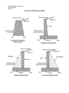
1 Injection mold DesignPart 4: Injection Molding CurriculumInjection mold DesignMold Design Common terms used to describe the tool used to produce Injection molded parts. Injection Molds are constructed from hardened steel, pre-hardened steel, aluminum,beryllium-copperalloy. In general, steel cost more to construct, but their longer lifespan will offset the higher initial cost over a higher number of parts made before wearing out. Injection Molds / Tool can be manufactured either by CNC machining or by using electrical discharge machining The consists of two primary components, the Injection (A plate) and the ejector (B plate).DesignConsideration Shrinkage allowance: Depends on shrinkage property of material core and cavity size. Cooling circuit: In order to reduce the cycle time, water circulates through holes drilled in both the core and cavity plates. Ejection gap: The gap between the ejector plate face and core back plate face should hold dimension within the core.
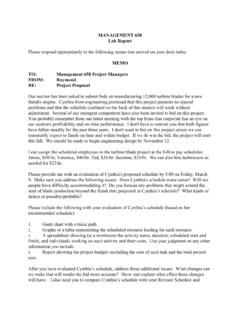
2 It must allow component to be fully removed from the mold polishing: The core, cavity, runner and sprue should have good surface finish and should be polished along material flow direction. mold filling: The gate should be placed such that the component is filled from the thicker section to thinner section. Draft: Required in both the core and cavity for easy ejection of the finished Steps 2. Parting line3. CoreCavity3. Number of CavityEjector systemCooling SystemMold Structure: Parting line A dividing line between a cavity plate and a core plate of a mold . - Make a parting line on a flat or simple-curved surface so that flash cannot be generated. - Venting gas or plate moldOne parting lineThree plate moldTwo parting linesMelt Delivery Gate Delivers the flow of molten plastics. Quickly cools and solidifies to avoid backflow after molten plastics has filled up in the cavity.
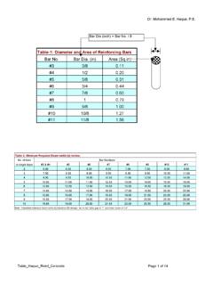
3 Easy cutting from a runner Location is important to balance flow and orientation and to avoid = mmh(thickness) = n A1/230 Runner cross sectionRunner cross section that minimizes liquid resistance and temperature reduction when molten plastics flows into the cavity. Too big Longer cooling time, more material, cost Too small short shot, sink mark, bad quality Too long pressure drop, waste, coolingHot runner, runnerless moldRunner balancingBalancedNot balancedDefectsMolding defects are caused by related and complicated reasons asfollows:* Malfunctions of molding machine* Inappropriate molding conditions* Flaws in product and mold Design * Improper Selection of molding materialWeldline Thisisa phenomenonwherea It Flashesdevelopatthemoldpartinglineorejec torpininstallationpoint. It Injectionpressureis toohigh,orclampingforceis Avoidingexcessivedifferencein thicknessis mosteffective.
4 Slowdowntheinjectionspeed. Applywell-balancedpressuretothemoldtoget consistentclampingforce,orincreasethecla mpingforce. Enhance the surface quality of the parting lines, ejector pins and shot Thisis thephenomenonwheremoltenplasticsdoesnotf illthemoldcavitycompletely. andtheportionof Theshotvolumeorinjectionpressureis notsufficient. Injectionspeedis soslowthatthemoltenplasticsbecomessolidb eforeitflowstotheendof Apply higher Injection pressure. Install air vent or degassing device. Change the shape of the mold or gate position for better flow of the This deformation appears when the part is removed from the mold and pressure is Uneven shrinkage due to the mold temperature difference (surface temperature difference at cavity and core), and the thickness difference in the part. Injection pressure was too low and insufficient Take a longer cooling time and lower the ejection speed.
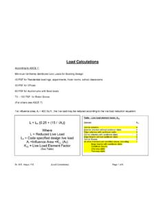
5 Adjust the ejector pin position or enlarge the draft angle. Examine the part thickness or dimension. Balance cooling lines. Increase packing marks-Equal cooling from the surface-Secondary flow-Collapsed surface Sink Marktstts< tConsiderations in Design of Injection molded partsGuideline (3)gate location determines weld linesweld lines* Source: Molding: molds with moving cores and side-action cams- If the geometry of the part has Structure: Undercut, Slide coreDesigning Injection molds: Typical Features[source: ] (a) Shut-off hole:no side action required(b) Latch:no side action required(c) Angled Latch:Side action cam required(a) Shut-off hole:no side action required(b) Latch:no side action required(c) Angled Latch:Side action cam requiredDesigning Injection molds: Typical Features