Transcription of INSPECTION CONCRETE AND MASONRY …
1 6/7/20111 INSPECTIONOFCONCRETEANDMASONRYCONSTRUCTI ONL esson 1 Requirements of Part 1203 Provisions shall be made for INSPECTION of the followingfollowing .. (a)(1)Building Permits required for work that must conform to the Code Building Permit ExemptionsBuilding Permits Must be adopted in the local regulation Does not exempt applicant from meeting Code requirements when applicableConstruction Documents Construction documents shall notbe accepted unless: Meet State Education requirementsSufficientdetailandclarity Sufficient detail and clarity Substantiate the work is code compliant Site plan Existing buildings, wells, septic tanks, location of work, distances Why do we Inspect? Ensure compliance with the approved plans Ensure that the owner gets what they paid for Control or manage the activities to assist the iconstruction process Record the processRequired Inspections (b)(1) work done under a permit shall remain exposed until inspected Permit holder shall notify CEO when work is readytobeinspectedready to be inspected (b)(2) required inspections:6/7/20112 Provisions shall be made for INSPECTION of the following.
2 (i) work site prior to the issuance of a permit;(ii) footing and foundation;Construction Inspections(iii) preparation for CONCRETE slab;(iv) framing;(v) building systems, including underground and rough in;(vi) fire resistant construction;(vii) fire resistant penetrations;(viii) solid fuel burning heating appliances, chimneys, flues or gas vents;(ix) energy code compliance; and(x) a final INSPECTION after all work has been prior to issuing the permitFootingsFoundationsConcretePrepara tion for the CONCRETE slabBuilding systems underground and rough in6/7/20113 CONCRETE PlacementFinished SlabAfter INSPECTION (3) notify permit holder if work is satisfactory or not Work not in compliance remains exposed until corrected, reinspected and found to be satisfactory Common Errors Failure to properly identify soil conditions and bearing capacity Design based solely on soil strength FailuretocreateuniformbearingconditionsF ailure to create uniform bearing conditions Over excavation Footing CONCRETE placed on frozen groundMore Errors Footing CONCRETE placed in mud Lack of reinforcement at steps Unprotected footing drains Uncontrolled foundation backfill Allowing deep clay deposits to dryCourse Goals Develop an awareness of soil load bearing capacities Review Code requirements for footings and foundationspacesfoundation spaces Explore various types of foundation walls Review INSPECTION requirements for CONCRETE and MASONRY Construction6/7/20111 Lesson 2 Foundation Requirements Must carry all loads Transmit loads Besupportedbypropersoils Be supported by proper soils fill sections must be designed.
3 Installed and tested per accepted engineering practiceHow do we fix this?Soil If soils are known to be of poor quality If soil conditions are unknown soilstestingbyanapprovedagencyshallbereq uiredto soils testing by an approved agency shall be required to determine soil bearing values for the siteIn lieu of a full geotechnical evaluation the loadbearingPresumptive Valuesload bearing values in table shall be assumedFoundation and Soil Investigations Purpose is to classify soil to determine its bearing properties Typical, known soils just classifySGif INVESTIGATE if Unusual soils/conditions Unknown soil6/7/20112 Investigation Methods Test pits Penetrometer Soil boring and samplingsampling Subsurface explorations Additional studiesSoil BoringsInvestigations The following comes from the soil engineer s commentary: Proposed Building Foundation: recommended to be continuous strip column footings and individual column footings, as needed.
4 Exterior strip column footings are suggested to include excavating a foundation trench that is centered about the gwall column centerline. Exterior footings are suggested to extend to a minimum depth of four feet, or as required by local code, below adjacent exterior ground surface. Discontinuous or "jump" footings are not recommended. Where needed, step footings, should have a rise to run ratio of 1 :2, Soil Boring Report Soil Engineer s report must be followed Incorporated into working drawings Discrepancies must be addressedCiid Corrections required6/7/20113 Removal of Soils Compressible or shifting soils must be removed to a sufficient depth and width expansive SoilsNew York State Department of StateFoundations on ExpensiveSoils Foundations and floor slabs for buildings located on expansive soils shall be designed in accordance with section of the Building Code of New fgfYork State Exception systems which have performed adequately in similar soil conditionsSlab Footing6/7/20111 Lesson 3 For For copy of prints on sitecopy of prints on site Posted building permitPosted building permitAs you enter site remember to checkAs you enter site remember to check Posted building permit Posted building permit Setback distancesSetback distances Topography of site Topography of site Soil conditions on siteSoil
5 Conditions on site Forms must be set on undisturbed soilForms must be set on undisturbed soil Must be sized as shown on printsMust be sized as shown on prints Footings must be set at the proper elevationFootings must be set at the proper elevationSetting the formsSetting the forms Footing top surface must be levelFooting top surface must be level Bottom of footing must have square edgesBottom of footing must have square edges Bottom of footings must be within 10 degrees of Bottom of footings must be within 10 degrees of level level or stepped footings will be requiredor stepped footings will be requiredCheck forCheck for Proper footing widthProper footing width Proper footing depth Proper footing depth Reinforcing bar size Reinforcing bar size Reinforcing bar placementReinforcing bar placementWall Support All exterior walls shall be supported by continuous footings FootingmustbesizedtosupportallloadsFooti ng must be sized to support all loads based on the soil characteristics Footings must be on undisturbed natural soil or engineered fillSection Footing Size Spread footings Minimum 6 thick Width (W) Table Projection (P) Minimum 2 Max.
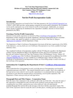
6 Thickness of footing Pier footing size Based on tributary loadsFigure (1)6/7/20112 Other Footing Requirements: Pier and Column Requirements Sizes based on tributary load and allowable soil pressure Tributary loadThldth tthlt The load that the column supports Soil load bearing value Tributary load soil load bearing value = minimum SF size of column footingTributary load soil load bearing value = minimum SF size of column footingTributary Load 6,000 is the minimum SF size of column footing?If footing is 4 SF and li4ih htSoil load bearing value1500 lbs6,000 1,500= 4 SFsize of column footing?column is 4 inches, what is the minimum thickness of the footing?T = 10 inchesBC Footing Design Minimum dimensions based on Building Code or designer s specifications Load bearing value of soilTg Material used Width of foundation wall W = width of footing T = thickness of footing P = Projection on either side of foundation wallBC Footing Design.
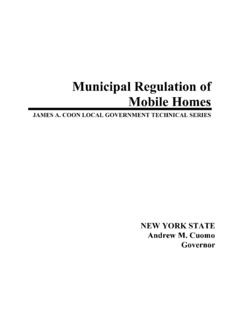
7 So designed that the allowable bearingcapacity of the soil is not exceeded. The minimum width of footings shall be 12 inchesSee1805 4 1 See1805 4 1inches. See The minimum thickness of footings shall be 8 inches. *See Footings in expansive designed in accordance See of Footing:NONE at Slab on Grade May be proposed due to regional preference May be REQUIRED due to soil characteristicsExterior Footing Requirements:Depth Below Frost Placed below frost line Prevents frost heave and settlement Exceptions: Frost protected footings Footings/foundations on solid rock Free standing buildings Meeting all 3 conditions Never placed on frozen ground6/7/20113 Footing Depth MUST be MaintainedFinish GradeMinimum cover Minimum required depth to coverMaintain required coverat exposed wallcoverStepped footingsMaintain req d coverRequired footing coverFooting Depth MUST be MaintainedMinimum cover Minimum required depth to coverFinish GradeMaintain required coverat exposed wallStepped footingscoverMaintain req d coverRequired footing coverBottom of footings cannot not exceed 1 in 10 ratioFootings on or Adjacent to Slopes Requirements for buildings on or adjacent to slopes steeper than Common Won t Work:Deep Foundation SystemsDistance to useable stratum too great for shallow foundationSituation with high potential for erosion makes shallow foundation undesirableWhen Common Won t Work.
8 Deep Foundation SystemsUpper strata suitable for bearingBut underlying soil subject to excessive settlementRequires use of lower, denser stratum to assure control of settlementTypes of Footings:Deep Foundation System Piles Specialized footing Transfers load through poor soil to deeper soil of adequate strength Usuallypre castanddrivenUsually precast and driven Materials used for pile footings Cast in place CONCRETE Pre cast CONCRETE Steel H piles Treated wood 6/7/20114 Types of Footings:Piers Specialized footing Short columns below grade transmit load to footingSl Several advantages over conventional foundationsJump Footings & Grade BeamsREQUIRE ENGINEERING6/7/20111 Lesson 4 Foundation Wall Design IF CONCRETE or Masonary May be ENGINEERED (Chapter 19 or 21) Within certain LIMITATIONS, a prescriptive design is permitteddes gspe tted Laterally supported top and bottom Tables (1) through (5) If Seismic Design Category C or worse.
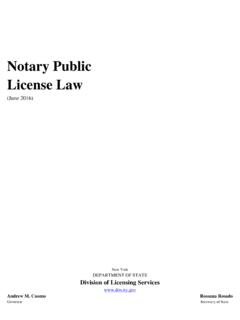
9 ADDITIONAL limitations applySee the Prescriptive Method is Allowed, through Foundation wall thickness based on What it supports The soil s characteristics Wall s depth and height Materials used in the foundation Reinforcing and compressive strengths Reinforcement alternatives Unbalanced Backfill The difference in height of the exterior and interior finish ground levels. g Where an interior CONCRETE slab is provided, height is measured from the exterior finish ground level to the top of the interior CONCRETE in Building and Residential Codes Should not be used if any of the following conditions exist: Soils which are unidentifiedFillsectionsthatwerenotengin eeredorproperly Fill sections that were not engineered or properly compacted Soils which are subject to settlement expansive soils, (these are soils that shrink and swell with change in moisture content) Highly compressive clays Unconfined sands and silts6/7/20112 Table (1) Plain MASONRY Foundation WallsMAXIMUM WALL HEIGHT (feet) MAXIMUM UNBALANCED BACKFILL HEIGHTc(feet) PLAIN MASONRYaMINIMUM NOMINAL WALL THICKNESS (inches)
10 Soil classesbGW, GP, SW and SP GM, GC, SM, SM-SC and ML SC, MH, ML-CL and inorganic CL 546 soliddor 86 soliddor 86 soliddor 856 soliddor 8810646 soliddor 86 soliddor 86 soliddor 856 soliddor 881068101246 soliddor 88856lidd81010756 soliddor 810106101210 solidd71210 solidd12 solidd846 soliddor 86 soliddor 8856 soliddor 810126101212 solidd71212 soliddFootnote e810 solidd12 soliddFootnote e946 soliddor 86 soliddor 885810126101212 solidd71212 soliddFootnote e812 soliddFootnote eFootnote e9 Footnote eFootnote eFootnote eMAXI WALL HEIGHT (feet) MAXIMUM UNBALANCED BACKFILL HEIGHTb(feet) Minimum Vertical Reinforcement Size and Spacingc, d, e, f, lSoil classesaand design lateral soil (psf per foot of depth) GW, GP, SW and SPGM, GC, SM, SM-SC and MLSC, ML-CL and inorganic CL30 45 60 Minimum wall thickness (inches) 4 PCPCPCPCPCPCPCPCPC5 PCPCPCPCgPCPCPCPCPCTABLE (5) CONCRETE FOUNDATION WALLSh, i, j, k86 PCgPCPCPCPCPC#5@43 PCgPC7 PCPCPC#5@41 PCPC#6@43 PCPC8#5@47 PCgPC#6@43 PCPC#6@32 #6@44 PCFootnotes d.