Transcription of Installation & Maintenance Instructions - Lesman
1 Page1of6(Section1of2)All Rights ValvesEASCO Valve, Hanover Road, Florham Park, New Jersey 07932 & Maintenance InstructionsSERIESI&M , GENERAL PURPOSE, WATERTIGHT/EXPLOSIONPROOF SOLENOIDS8003G/H8202G/Hr(Section1of2) SERVICE NOTICE ASCO rsolenoid valves with design change letter G or H in the catalog number (ex. 8210G1) have an epoxyencapsulated ASCOrRed Hat IIrsolenoid. This solenoidreplaces some of the solenoids with metal enclosures andopen---frame constructions. Follow these Installation andmaintenance Instructions if your valve or operator uses separate Instructions for basic numbers 8003G/H and 8202G/H are epoxyencapsulated pull---type solenoids. The green solenoid withlead wires and 1/2 Iconduit connection is designed to meetE n c l o s u r e Ty p e 1 --- G e n e r a l P u r p o s e , Ty p e 2 --- D r i p p r o o f ,Ty p e s 3 a n d 3 S --- Ra i n t i g h t , a n d Ty p e s 4 a n d 4 X --- Wa t e r t i g h t.
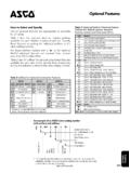
2 The black solenoid on catalog numbers prefixed EF or EV is designed to meet Enclosure Types 3 and3 S --- Ra i n t i g h t , Ty p e s 4 a n d 4 X --- Wa t e r t i g h t , Ty p e s 6 a n d6P---Submersible, Type 7, Explosionproof Class I, Division1 GroupsA,B,C,&DandType9,---Dust---Ignitio nproofClass II, Division 1 Groups E, F & G. The Class II, GroupsF & G Dust Locations designation is not applicable forsolenoids or solenoid valves used for steam service or whena class H solenoid is used. SeeTemperature Limitationssection for solenoid identification and nameplate/retainerfor service. When installed just as a solenoid and notattached to an ASCO valve, the core has a tapped hole, or minimum full :Catalog number prefix EV denotes stainless catalog numbers 8202G/H1, 8202G/H3, 8202G/H5and 8202G/H7 are epoxy encapsulated push---type,reverse---acting solenoids having the same enclosure typesas previously stated for Catalog numbers 8003G/H1 and8003 8003G/H and 8202G/H solenoids are available in:SO p e n --- Fr a m e C o n s t r u c t i o n :The green solenoid may besupplied with 1/4 Ispade, screw or DIN terminals.
3 (Referto Figure 4)SPanel Mounted Construction:These solenoids arespecifically designed to be panel mounted by thecustomer. Refer to Figures specified in this I&M and thesection onInstallation of Panel Mounted Features For Type 1 --- General PurposeConstruction OnlySJunction Box:This junction box construction meetsEnclosure Types 2, 3, 3S, 4, and 4X. Only solenoids with1/4 Ispade or screw terminals may have a junction junction box provides a 1/2 Iconduit connection,grounding and spade or screw terminal connectionswithin the junction box (See Figure 5).SDIN Plug Connector Kit :Use this kit onlyfor solenoids with DIN terminals. The DIN plugconnector kit provides a two pole with groundingcontact DIN Type 43650 construction (See Figure 6).OPERATIONS eries 8003G/H --- When the solenoid is energized, the coreis drawn into the solenoid base : When the solenoid is de---energized, theinitial return force for the core, whether developed byspring, pressure, or weight, must exert a minimum force toovercome residual magnetism created by the return force for ACconstruction is 11 ounces, and5 ounces for DC 8202G/H --- When the solenoid is energized, the discholderassembly seatsagainst theorifice.
4 When thesolenoidis de---energized , the disc holder assembly : Initial return force for the discor discholderassembly, whether developed by spring, pressure, or weight,must exert a minimum force to overcome residualmagnetism created by the solenoid. Minimum return forceis 1 pound, 5 nameplate for correct catalog number, service, andwattage. Check front of solenoid for voltage and :Electrical hazard from the accessibilityof live parts. To prevent the possibility of death, seriousinjury or property damage, install the open --- framesolenoid in an :To prevent fire or explosion, do notinstall solenoid and/or valve where ignitiontemperature of hazardous atmosphere is less than165_C. On valves used for steam service or when aclass H solenoid is used, do not install in hazardousatmosphere where ignition temperature is less than180_C.
5 See nameplate/retainer for :These solenoids have an internal non---resetablethermal fuse to limit solenoid temperature in the event thatextraordinary conditions occur which could cause excessivetemperatures. These conditions include high input voltage,a jammed core, excessive ambient temperature or a shortedsolenoid, etc. This unique feature is a standard feature onlyin solenoids with black explosionproof/dust---ignitionproofenclo sures (Types 7 & 9).CAUTION:To protect the solenoid valve oroperator, install a strainer or filter, suitable for theservice involved in the inlet side as close to the valveor operator as possible. Clean periodically dependingon service conditions. See ASCO Series 8600, 8601,and 8602 for 2 of 6 ( 1 of 2)I&M Valve, Hanover Road, Florham Park, New Jersey 07932 LimitationsFor maximum valve ambient temperatures, refer to temperature limitations listed, only indicate maximumapplication temperatures for field wiring rated at catalog number prefix and watt rating on nameplateto determine maximum ambient temperature.
6 See valveinstallation and Maintenance Instructions for maximumfluid :For steam service, refer toWiringsection,JunctionBoxfor temperature rating of supply Limitations For Series 8003G or 8202G Solenoidsfor use on Valves Rated at , , , or WattsWattRatingCatalogNumber Coil PrefixClass ofInsulationMaximum[Ambient & ,FB,KF,KPSC, SD, SF, & SP,F125_F ( ) & ,HT,KB,KH,SS, ST, SU,H140_F(60_C) & ,FB,KF,KP,SC, SD, SF, & (40_C) & ,HT,KB,KH,SS,ST,SU,&SVH104_F(40_C)[Minim um ambient temperature ---40_F ( --- 4 0_C).Coil Class140 Wattage Ratings(_F)(_C)HT60 Hz50 HzMax. AmbientTemperatureFBEF, EVACDC---6052131---55125 FBFTFTT emperature Limitations for series 8002H/8003 Hsolenoids (Catalog Numbers 8262H & 8263H valves)PrefixEF, EV------HBHTHBHTHBHTHBEF, EVEF, EVEF, EVEF, EV =EF, EV data applies to Explosionproof coils only.]]
7 =DC solenoid valves can be operated at maximum ambient temperature of55_C / 131_F with reduced pressure ratings. See valve I&M for maximumoperating pressure differential ratings. =Steam Service Valves have a maximum ambient temperature of 55_ solenoid is designed to perform properly whenmounted in any position. However, for optimum life andperformance, the solenoid should be mounted vertically andupright to reduce the possibility of foreign matteraccumulating in the solenoid base sub---assembly must comply with local codes and the NationalElectrical Code. All solenoids supplied with lead wires areprovided with a grounding wire which is green or green withyellow stripes and a 1/2 Iconduit connection. To facilitatewiring, the solenoid may be rotated 360_.
8 For the watertightand explosionproof solenoid, electrical fittings must beapproved for use in the approved hazardous :Cryogenic Applications --- Solenoid leadwire insulation should not be subjected to cryogenictemperatures. Adequate lead wire protection androuting must be Wiring Instructions For OptionalFeatures:SOpen---Frame solenoid with 1/4 Ispade solenoids supplied with screw terminal connections use#12---18 AWG stranded copper wire rated at 90_Corgreater. Torque terminal block screws to 10 2 in---lbs[1,0 1,2 Nm]. A tapped hole is provided in the solenoid forgrounding, use a #10---32 machine screw. Torque groundings c r e w t o 1 5 --- 2 0 i n --- l b s [ 1 , 7 --- 2 , 3 N m ] . O n s o l e n o i d s w i t hscrew terminals, the socket head screw holding the terminalblock to the solenoid is the grounding screw.
9 Torque thes c r e w t o 1 5 --- 2 0 i n --- l b s [ 1 , 7 --- 2 , 3 N m ] w i t h a 5 / 3 2 Ihex key BoxThe junction box is used with spade or screw terminalsolenoids only and is provided with a grounding screw anda1/2 Iconduit connection. Connect #12---18 AWGstandardcopper wire only to the screw terminals. Within the junctionbox use field wire that is rated 90_Corgreaterforconnections. For steam service use 105_Cratedwireupto50 psi or use 125_C rated wire above 50 psi. After electricalhookup, replace cover gasket, cover, and screws evenly in a crisscross Plug Connector Kit to accommodate the plug connector Remove center screw from plug connector. Using a smallscrewdriver, pry terminal block from connector Use #12---18 AWG stranded copper wire rated at 90_Cor greater for connections.
10 Strip wire leads backapproximately 1/4 Ifor Installation in socket use of wire---end sleeves is also recommended forthese socket terminals. Maximum length of wire---endsleeves to be approximately 1/4I. Tinning of the ends ofthe lead wires is not Thread wire through gland nut, gland gasket, washer andconnector :Connector housing may be rotated in 90_increments from position shown for alternate positioning ofcable Check DIN connector terminal block for electricalmarkings. Then make electrical hookup to terminal blockaccording to markings on it. Snap terminal block intoconnector cover and install center Position connector gasket on solenoid and install plugconnector. Torque center screw to 5 1 in---lbs [0,6 1,1Nm].NOTE:Alternating current (AC) and direct current (DC)solenoids are built differently and cannot be converted fromone to the other by changing the (Section1of2)I&M Valve, Hanover Road, Florham Park, New Jersey 07932 of SolenoidSolenoids may be assembled as a complete unit.