Transcription of Installation & Maintenance Manual MECHANICAL …
1 7/27/2018 TORQLIM_MECH_W_COUPL_MANUAL Page 1 of 6 Installation & Maintenance Manual MECHANICAL friction TORQUE LIMITER MECHANISMS WITH COUPLINGS Catalog Products: V2G2R-STL V3G2H-STL V4G2H-STL V5G2H-STL V6G1G-STL, V6G2G-STL V8G1K-STL, V8G2K-STL And non-catalog variations of this torque limiter design. Mach III Technical Support Toll Free: 866-291-0849 International: 001-859-291-0849 Email: Detail sheets and 3D models are available on the Mach III website: Please contact Mach III to obtain assembly and parts list drawings.
2 These products include rotating equipment and should be guarded according to OSHA requirements and other Federal, State and local regulations. It is the responsibility of the user to provide the necessary guarding. Mach III Clutch, Inc. All Rights Reserved CLICK on product numbers above to obtain the product detail sheet which includes dimensional data helpful during Installation . 7/27/2018 TORQLIM_MECH_W_COUPL_MANUAL Page 2 of 6 I. Torque Setting Mach III torque limiters are typically shipped to the customer with the torque value they have specified.
3 (Note: All torque settings are +/- 10%.) If a torque limiter requires setting or re-setting in the field, please refer to section VII of this document. II. Torque Limiter Installation Great care must be exercised to assure proper offset & angular alignment between shafts to prevent premature coupling failure. Dimensional diagrams can be obtained by using links on page one of this Manual . A. SHAFT PREPARATION & MOUNTING Mach III Clutch products are bored to fit a precision plug gauge for the specified bore size and should slide fit the mating shaft.
4 Make certain that the shaft is free of burrs or nicks. It may be necessary to file or sand the shaft to assure a slide fit. Never hammer the torque limiter onto the shaft. Hammering on the torque limiter may cause evident damage or subtle injury that will shorten the wear life of the unit, and will void the warranty. (1) Apply the anti-seize (E-Z Break ) lubricant from the packet provided, or equivalent, to the shaft. (2) Insert key (customer supplied) onto the shaft. (3) Slide torque limiter over key on the shaft, align the sprocket or pulley.
5 (4) Tighten set screws to secure the torque limiter to the shaft. B. FINAL INSPECTION & TESTING After a short run, check set screws and alignment. III. Torque Limiter Operation This is a manually adjusted torque limiter. Torque is proportional to the amount of spring compression. Special Note Regarding friction Disc Contamination: The friction material used in this product will absorb oil, water, chemicals and other contaminants. Depending on the type of contamination, torque limiter may either seize up entirely or lose torque capacity.
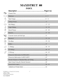
6 If friction discs become contaminated, they should be replaced. See repair kit ordering information below. IV. Routine Maintenance When installed and operated according to the preceding guidelines, Mach III Clutch products should require little or no routine Maintenance . A repair kit is available which contains all parts subject to typical wear: friction discs, springs. 7/27/2018 TORQLIM_MECH_W_COUPL_MANUAL Page 3 of 6 RETAINER RINGDRIVE DISCCOUPLINGFRICTION DISCDRIVE HUBNYLON SCREWSPRINGNUTSET SCREWSW/JAM NUT (some models) V.
7 Parts diagram Repair Kit: Part number = Clutch product Number + -RPRK ( V3G2H-STH-RPRK) Facing Kit: Part number = Clutch product Number + -FCGK ( V3G2H-STH-FCGK) Additional Parts: Contact Mach III to obtain a complete listing of additional parts kits available for your specific clutch. Please reference product number when calling or e-mailing. Repair services: Factory repair is available. A return materials authorization (RMA) number must be obtained prior to sending any unit in for repair VI. Repair Kit Installation Procedure Tools Required Hex Wrench Set Retainer (snap) Ring Pliers Spanner Wrench Compounds Required Anti-Seize Lubricant (for re- Installation ) A.
8 DISASSEMBLY (1) Remove torque limiter from shaft and place in vertical position with nut end facing upward. (2) Loosen nylon point set screw, set screws and jam nuts (some models) and remove nut. Drive hub will need to be held stationary for this procedure. (3) The disc package (consisting of spring, drive discs and friction discs) will now be accessible. B. friction DISC & SPRING REPLACEMENT (1) Remove the spring, drive discs and friction discs. (2) Drive discs should be clean, dry and free of burrs or nicks.
9 (3) Reassemble drive & friction disc section according to reference drawing using new spring, drive discs & friction discs as necessary. (4) Assure that drive discs move freely on the drive hub and that the lugs of the friction disc discs move freely in the drive slots of the sleeve. 7/27/2018 TORQLIM_MECH_W_COUPL_MANUAL Page 4 of 6 C. REASSEMBLY (1) Replace the nut. (2) Adjust to desired torque. (3) Tighten nylon point set screw. (4) See torque Limiter Installation portion of these instructions for the proper procedure for reinstalling the clutch.
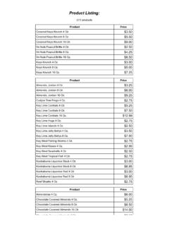
10 VII. Torque Setting Instructions A. product Numbers: V3G2H-STL, V4G2H-STL, V5G2H-STL and non-catalog variations of this torque limiter design. (1) Make sure the nylon-tipped set screw (REF. C) in the outside diameter of the adjustment nut (REF. A) is loose. (2) Make sure the adjustment nut (REF. A) is snug against the disc spring (REF. B). (3) Using a spanner wrench, tighten the adjustment nut (REF. A) against the disc spring (4) Check torque value after each 1/4-turn increment of the adjustment nut (REF.)