Transcription of INSTALLATION AND MAINTENANCE …
1 2 Class 300 25-Series Pressure Regulator4. Install a small gate valve in the sensing line so that this can be closed when servicing the The sensing line must be pitched downward from the-main valve to insure proper To permit accurate setting of the pressure regulator, a pressure gauge should be installed as close as pos-sible to the pilot sensing line A bypass connection, as shown in Figs. 1, 2 and 3 is recommended so that the valve can be serviced with-out shutting down the The bypass valve should be the same size as the pressure Line Drain Trap1. To insure proper operation of the valve and avoid premature wear, it is recommended that a 1/2 Spirax Sarco thermodynamic steam trap be installed on the steam supply line.
2 (See Figs. 1, 2 and 3.)2. A steam trap should also be installed in the down-stream piping at the heel of each rise, between all reducing valves installed in series, and ahead of any manual or automatic valve. This will prevent conden-sate accumulation that can result in waterhammer Strainers1. It is strongly recommended that strainers be installed before the reducing valve and steam Make certain adequate clearance is provided for screen removal and blowdown connection between strainer and valve ValvesAll stop valves on the supply side, as well as on the downstream side of the pressure reducing valve and sensing line, should be of the gate type so as to insure full rated capacity and good It is strongly recommended that separators be installed upstream of regulator complete with trap set.
3 (For more information, refer to IMI )2. See Fig. 3 for proper CarefullyDo not lift the regulator by the tubing. Grasp the body of the valve firmly when lifting. If installed, do not lift the regulator by the tubing. Piping1. Typical hookup sketches as shown in Figs. 1, 2 and 3 will aid in planning a correct Piping on the downstream side of the valve should be increased so as not to restrict flow. See Steam Velocity Chart for recommended pipe Swage nipples are recommended for changes in pipe Before installing the valve make sure the piping is free of foreign material, scale, Make certain the arrow cast on valve body is pointing in the direction of Valve should always be installed in a horizontal posi-tion.
4 (See Figs. 1, 2 and 3.)7. Press gauges installed on both Pilot to Valve Body1. Remove all protective caps from ports if Remove the package of square gaskets from the pilot box and install on the main valve cover assembly (A).3. Install pilot on top of gasket just placed on main valve cover assembly (A) so that the sensing line is pointing in same direction as the valve outlet connection. Be sure that the guide pin in the cover assembly (A) fits securely in the guide hole in the pilot. Be sure the pilot bolts are secured to the valve cover assembly (A) and Pressure Sensing Line1.
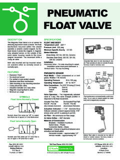
5 Copper or stainless steel tubing (1/4 OD) can be used for the sensing line with suitable compression fittings or as alternative 1/4 piping can be Connect the sensing line to a straight portion of the piping 10 pipe diameters from the nearest fitting down-stream from the valve and approximately 1 foot from elbows, tees, valves and other restrictions. (See Figs. 1, 2 and 3.)3. When the reducing valve is serving a single piece of equipment, the sensing line can be connected to the steam space of the AND MAINTENANCE INSTRUCTIONSIM-3-100-US July 20152 Select inlet piping for reasonable velocity and expand downstream for equal flow lead valve 2 psi above desired set pressure and set lag valve 2 psi below desired set OperatedPressure Control ValveFloat &Thermostatic Steam TrapMoisture SeparatorPressureSensing LineReducedSteamPressureCheck
6 ValveDripPanElbowReducedSteamPressureStr ainerTypical Pressure Reducing Valve StationStrainerSteamSupplyParallel Operation ofPressure Reducing ValvesSpira-tecLoss DetectorStrainerSafetyValveSteamSupplyPi lot OperatedPressure Control ValveStrainerStrainerFloat &Thermostatic Steam TrapMoisture SeparatorPressureSensing LineCheck ValveDripPanElbowMoistureSeparatorReduce dSteamPressureCheck ValveDripPanElbowSeries Pressure Reducing Valve Station for High Turndown RationsNote: Intermediate pressure takeoff requires an additional safety DetectorStrainerSafetyValvePilot OperatedPressure Control ValvePilot OperatedPressure Control ValveStrainerFloat &Thermostatic Steam TrapPressureSensing LineSpira-tecLoss DetectorStrainerFloat &Thermostatic Steam TrapPressureSensing LinePilot OperatedPressure Control ValveCheck ValveSpira-tecLoss DetectorSafetyValveFig.
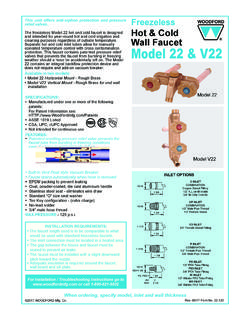
7 1 Fig. 2 Fig. 33 PressureAdjustment, Springor AirPressurePilotPressureDiaphragmDownstr eamPressureSensing LineOrificeMain ValveMain DiaphragmInletHow the 25P & 25PA WorkNormal positions before start-up are with the main valve closed and the pilot valve held open by spring force. Entering steam passes through the pilot valve into the main diaphragm chamber and also out through the control orifice. As flow through the pilot exceeds flow through the orifice, control pressure increases in the diaphragm cham-ber and opens the main valve. As steam flows through the main valve, the increase in downstream pressure feeds back through the pressure sensing line to the under-side of the pressure diaphragm.
8 When the force below that diaphragm balances the compression force of the spring above it, the pilot valve throttles. The control pres-sure maintained in the main diaphragm chamber positions the main valve to deliver just enough steam for the desired delivery pressure. Adjustment of the spring above the pressure diaphragm changes the downstream pressure set point. When steam is no longer required, the sensing line pressure increases closing the pressure pilot and the control pressure bleeds back through the control orifice. This allows the main valve to hold the desired reduced pressure, and it may close tight for a dead-end (Refer to Fig.)
9 5)1. First make certain that all stop valves are Remove pilot spring cover, then turn the pressure pilot adjustment (2D) counter-clockwise until spring is slack. Make certain spring remains in vertical position and centered in its retainers. Air Loaded PA Pilots must have no P supplied to Open stop valves in the following order: a. Open stop valve ahead of steam trap on steam supply line. This will insure water free steam at the regulator inlet when put into operation. b. Open small gate valve on pressure sensing line. c. Open downstream stop valve. d.
10 Slowly open inlet stop Slowly adjust pilot spring at (2D) turning clockwise until reduced pressure required is indicated on pressure gauge downstream of Once the system has stabilized itself, it may be nec-essary to make re-adjustment of pilot spring (2D). Replace spring cover, then tighten adjustment Important Retighten all pilot flange connections to insure steam tight joints. Recommended Torque 2A Screws 13-15 ft. lbs. 2C Screws 15-20 ft. Air Loading PA Pilot requires air loading as indicated in the following table:Control PressureDesired Outlet Steam 5 10 25 50 75 100 Pressure P2 psig Inlet Pressure P1 psigApproximate 11 16 31 56 80 102 Air Set Pressure to to to to to topsig 58 81 10310 psig to 100 psig4 Troubleshooting(Refer to Figs.)