Transcription of PNEUMATIC FLOAT VALVE - okcc.com
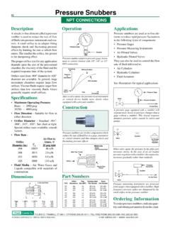
1 Normally closed FLOAT valves are "off" (no output)when FLOAT is low. Air signal is "on" when FLOAT is VALVE Normally OpenNormally open FLOAT valves are "on" when FLOAT islow. Air signal is "off" when FLOAT is VALVESPECIFICATIONSFLOAT AND BODYT emperature Limit 220 FPressure Limit 200 psigMinimum Specific Gravity SGWetted Materials Brass Body; 301 SS, 304 SS, Ceramic Stainless Steel Body; 303 SS, 301 SS, 304 SS, CeramicInstallationHorizontal VALVE For side mounting to vessel, Installation arrow must point downwardVertical VALVE For top SENSORF luid Media Clean compressed air or inertgases, filtration < 40 micronsOperating Pressure 30 to 100 psigOperating Temperature 35 to 140 FValve Connections For 3/32" ID tubing ( mm)Air SupplyPort #1 OutputPort #2 VentPort #3 VALVE Operation The magnetically actuatedvalve is 3 way.
2 The VALVE changes position inresponse to the FLOAT Flow PathDe-Actuated Flow PathPort #1 - Port #2 Port #3 - Port #2(Blue Indicator Extended)(Blue Indicator Retracted)Actuation Indicator 1/16" diameter/BlueIndicator extends outward (approximately 1/16"stroke) when port #1 is passing to port # Flow No continuous air flow VALVE Orifice .080" diameterMaterials of ConstructionBrackets Anodized AluminumSwitch Body PlasticConnection Barbs BrassDeadband Change in liquid level between valveactuation and models approximately 1/2"Vertical models approximately 1/4"DESCRIPTIONThe Magnetic FLOAT VALVE is an air sensor fordetecting liquid level inside a vessel. The floatmechanism mounted within the vesseloperates a ceramic coated magnet. As thefloat moves it pivots the magnet. A magneti-cally actuated sensor on the outside of thesolid metal housing reacts to the innermagnet movement.
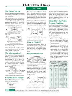
3 The movement shifts a3-way air side mounted and top mounted valvesare available either as normally closed ornormally Explosion Proof No electrical hazard For vented or non-vented vessels Stainless steel FLOAT mechanism Side mounting or top mounting selection 3-way PNEUMATIC VALVE Actuation indicator on 3 way VALVE Magnetic coupling- FLOAT to VALVE Minimum air usageSYMBOLSF loat VALVE Normally ClosedHorizontal FLOAT VALVE for side mounting to ves-sel. FLOAT operates air VALVE on outside of closed or normally mechanism is contained inside a solid metalbody. The air VALVE is located outside the metalbody and is magnetically FLOAT VALVE is mounted on top side ofclosed or vented vessels. Normally closed ornormally open versions available. O'Keefe Controls Co. 2007 All Rights ReservedFax(203) Box QTrumbull, CT 06611CT Phone (203) 261-6711website Maple DriveMonroe, CT 06468 Toll Free Phone (800) 533-32851" NPTT hreadSolidMetalBodyMagneticSensorSSFloat CeramicCoatedMagnetAirConnections213132 Controls KeefePNEUMATIC FLOAT VALVEHORIZONTAL FLOAT VALVE SIDE MOUNTINGVERTICAL FLOAT VALVE TOP MOUNTING6-7/8""1-3/8" Hex1" NPT1" Dia.
4 X 2" Lg. FloatCable Clamp BracketOKC-1532 OptionalTUBINGNOT INCLUDEDN ormally Closed Signal On Rising LevelNormally Closed Signal On Rising Level7-11/16"1" Dia. x 2" " NPT1-3/8" HexCable Clamp BracketOKC-1532 OptionalTUBINGNOTINCLUDEDPART NUMBERSC atalog FLOAT PressureOKC-1536-1 BrassSide Steel200 psigOKC-1536-2 Stainless SteelSide MountinOKC-1570-1 BrassTop Steel200 psigOKC-1570-2 Stainless SteelTop MountingOKC-2250-1 BrassSide Steel200 psigOKC-2250-2 Stainless SteelSide MountingOKC-2271-1 BrassTop Steel200 psigOKC-2271-2 Stainless SteelTop Steel200 psigHORIZONTAL FLOAT VALVE SIDE MOUNTINGVERTICAL FLOAT VALVE TOP MOUNTINGN ormally Open Signal On Falling LevelNormally Open Signal On Falling LevelTUBINGNOTINCLUDED132 SYMBOL "1-3/8" Hex1" NPT1" Dia. x 2" Clamp BracketOKC-1532 OptionalTUBINGNOT INCLUDED132 SYMBOL "7-11/16"1" Dia.
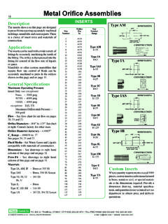
5 X 2" Lg. Float1" NPT1-3/8" HexCable Clamp BracketOKC-1532 Optional132 SYMBOL O'Keefe Controls Co. 2007 All Rights Reserved1" NPTC ontrols Steel200 Steel200 Steel200 psigLEVEL control NARROWBANDLEVEL control WIDEBANDN ormally closed FLOAT VALVE (side or top mounted). Output signal(port 2) of level sensor is "on" when level is high. Output can actu-ate an indicator, pressure switch, air pilot power VALVE , etc. Can beused with High Level Indicator panel shown on page 4. O'Keefe Controls Co. 2007 All Rights ReservedLEVEL INDICATOR AND control APPLICATIONSROTACIDNI LEVEL WOLROTACIDNI LEVEL HGIHN ormally open FLOAT VALVE (side or top mounted). Output signal (port2) of level sensor is "on" when level is low. Output can actuate anindicator, pressure switch, air pilot power VALVE , etc. Can be usedwith Low Level Indicator panel shown on page level sensors required; one normally closed for high level, onenormally open for low level.
6 The control automatically maintains thelevel between the location of the two sensors. Minimum "high/low"is approximately two inches. Maximum "high/low" is set by the loca-tion of the two sensors. Can be used with Wideband Level Controlpanel on page normally open FLOAT VALVE provides the control for narrowbandlevel control . Level is maintained within approximately 1/2". Outputcan actuate an air operated power VALVE for direct fill, or for controlof an air operated pump through an air operated power VALVE . Theoutput can be used with the Narrowband Level control panel shownon page ValveNormally ClosedFloat ValveDetentedAir ValveAir InAir InAir InNormally OpenFloat ValveDrainNormally OpenFloat ValveFillAir In12 DrainNormally ClosedFloat ValveIndicatorFillSignal "On" (Port 2)when level is InDrainNormallyOpenFloat ValveIndicatorFillAir In12121212 Fill ValveControls KeefeForm OK-242R2 O'Keefe Controls Co.
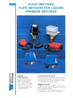
7 2007 All Rights ReservedHIGH LEVEL INDICATORThis panel is used for indication of level only. Whena normally closed FLOAT VALVE is actuated by highliquid level the indicator shows "red". The indicatorshows green when the FLOAT VALVE is not No. OKC-2289 FIncludes inlet filter, regulatorand gage No. OKC-2289 Filter, regulator and gage the high level indicator panel with a normallyclosed FLOAT OKC-1570-1 OKC-1536-2 OKC-1570-2 LOW LEVEL INDICATORThis panel is used for indication of level only. Whena normally open FLOAT VALVE is deactuated by lowliquid level the indicator shows "red". The indicatorshows green when the FLOAT VALVE is actuated by theliquid No. OKC-2290 FIncludes inlet filter, regulatorand gage No. OKC-2290 Filter, regulator and gage the low level indicator panel with a normallyopen FLOAT OKC-2271-1 OKC-2250-2 OKC-2271-2 SPECIFICATIONSO peration A pneumaticindicator panelBox Dimensions 4-1/2" x 2-7/8" x 2-5/8"Inlet Air Pressure to Regulator 50-125 psigNormal Pressure Setting 50-100 psigPneumatic Indicator 1" diameter red/greenManual control OFF/ON Toggle ValveAir Filtration Air should be dryand filtered to 5 micronsWIDEBAND LEVEL CONTROLThis panel is used for control of liquid between twolevels.
8 The control panel pilots a fill or drain VALVE , orcontrols a power VALVE that operates a pump. A normallyclosed FLOAT VALVE is used to sense the high level. Anormally open FLOAT VALVE is used to sense the low No. OKC-2291 FIncludes inlet filter, regulatorand gage No. OKC-3171F(same as OKC-2291F but configured for Pump Down operations.)OKC-2291F panel indicator shows green after the high level is reached and continues to indicate green until the low level is reached. After the low level sensor isdeactuated the indicator shows "red" until the high levelsensor is actuated. (OKC-3171F shows "red" during pumpdown.) NARROWBAND LEVEL CONTROLThis panel is used for control of liquid level over thedeadband of the PNEUMATIC FLOAT VALVE (approximately1/4" to 1/2"). The control panel pilots a fill or drain valvethat operates a pump. A normally open FLOAT VALVE is output control is "on" (indicator red) when the level islow and is "off" when the level is high (indicator green).
9 Part No. OKC-2292 FIncludes inlet filter, regulatorand gage No. OKC-2292 Filter, regulator and gage output signal can also be used as a remoteindicator signal to operate a visual indicator or a sonicalarm. Use as follows: Low Level Alarm use a normally open FLOAT valveHigh Level Alarm use a normally closed FLOAT valveTo LevelSensorTo HighLevel SensorTo LowLevel SensorHIGH LEVEL INDICATORLOW LEVEL INDICATORWIDEBAND LEVEL CONTROLNARROWBAND LEVEL CONTROLAir InAir InAir InAir InTo control Valveor PumpTo control Valveor PumpTo HighLevel SensorTo LowLevel SensorSPECIFICATIONSO peration A PNEUMATIC controlpanelBox Dimensions 4" x 4" x 2-5/8"Inlet Air Pressure to Regulator 50-125 psigNormal Pressure Setting 50-100 psigPneumatic Indicator 1" diameter red/greenManual control OFF/ON Toggle ValveAir Filtration Air should be dryand filtered to 5 micronsOutput Air Signal 50-100 psig(same as regulator pressuresetting)Controls KeefeWhen the panel indicator shows "green" the outputsignal is "off".
10 When the panel indicator shows "red" theoutput signal is "on."