Transcription of Installation and Operating Instructions
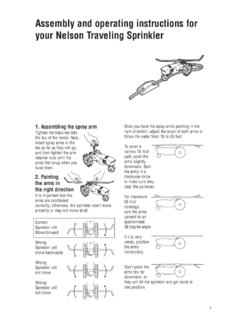
1 PARTSCATALOG2 HMitre Band SawInstallation and Operating InstructionsNote: Not all saw parts are shown in this booklet107 W. Railroad Street Box 930219 Verona, WI 53593-0219 Phone: (608) 845-6472 Fax: (608) 845-5199 COMPANY, CATALOG1-800-383-5547 Adjustable LegsChip TrayCart WheelCompensatingSpring AssemblySpeedReducerHead WeightAdjustmentPulley BoxDrive WheelEndMotorHydraulic FeedControlReplaceable Aluminum Saw TableMoveable Guide ArmAutomatic Shut-Off SwitchIdler Wheel EndT-HandleBlade TensionAdjustmentIdler SpindleAdjusting PlateBlade GuideAssembly-IdlerViseTelescoping Handlewith GripBearing Carrier AssemblyBLADEGUIDEPage 2*On all saws, except for the Model 4000, the stationary and adjustable kits are the same except for items 6, 16, and 15 which are included withthe adjustable kits.
2 On the Model 4000 there is no adjustable kit. Therefore, use part number 6747 for both bearing kits on the Model Number For Models9001000120090H11001440150016001800 200030004000 Item Guide Assembly, Drive EndComplete Guide Assembly, Idler End19016I5391558855885981 Housing Assembly, Idler255415541554155415541 Adjustment Stud, Bearing Plate3426042604260426042601/4-20 Hex. Nut460666066606660665999 Spindle, Pressure Bearing544994499449944994522 Ball Bearing, Pressure642604260426642664279 Nut, Washer, Spring843104310431043104311 Flat Washer, SAE942714271427142714270 Wing Nut or Stop Nut1053895389558760746073 Spindle, Guide Bearing1145224522450245024515 Ball Bearing, Guide1241404140414041408-32 x 3/8 Set Screw1342584258425842584260 Hex.
3 Nut1441554155415541554137 Socket Head Cap Screw154304 Flat Washer, 3/16 or 1/4 Washer1753745374554255426056 Guide Clamping Bolt189016D5390554055405982 Housing Assembly, Drive1990129012901290125996 Pressure Bearing Assembly2054065406673067426747 Stationary Guide Bearing Kit2154075407673267436747 Adjustable Guide Bearing KitBlade Guide AssemblyCompleteAssemblyCompleteAssembly Bearing OnlyStationary and Adjustable Guide Bearing Assemblies Pressure Bearing Assembly For Replacing Bearings in Blade Guides, Order 2 Each of Parts 19, 20, 21 # 19 # 20 # 21 Idler End Idler End Drive End * *Not part of Assy. kit Drive End Saw Models Part # 1600, 1800, 2000, 3000 9012 4000 5996 Saw Models Part # 1600, 1800, 2000, 3000 6742 4000 6747 Saw Models Part # 1600, 1800, 2000, 3000 6743 4000 6747 Stationary Bearing Assy.
4 Adjustable Bearing Assy. For other models, See page 2 Drive EndIdler End1-800-383-5547 HYDRAULICFEEDCONTROLPage 3 Ellis Mfg. Company, Inc. 107 W. Railroad Street Box 930219 Verona, WI 53593-0219 Phone: (608) 845-6472 Fax: (608) 845-5199 Number For Models15001600180090H9001000110012001440 200030004000 Item Feed Control Assembly15529552955295529 Cap24950495049504950O-Ring-Shaft35532553 255325532 Sealing Washer, Top44951495149514951O-Ring-Cylinder55361 553055305766 Shaft64337433743374337 Lock Washer, 5/1675531553155315531 Sealing Washer, Bottom85533553355335533 Leather Cup95534553455345534 Washer-Special104266426642664266 Nut, Hex. Jam, 5/16-24115362552855285767 Cylinder124743474347434743 Plug, Oil Fill134730473047304730 Male Elbow - Tube Fitting144732473247324732 Sleeve154729472947294729 Nut165363559057115706 Tube, 1/4 Dia.
5 Plastic1747314731 Needle Valve-Tube Fitting184728472847284728 Male Elbow Assembly19*47274727 Needle Valve Assembly205356574957495748 Travel Stop Tube216702670267026702 Rebuilding Kit2257075707 Remote Needle Valve Assembly23*48084808 Flow Needle Valve Assembly2447354735 Elbow, Male to Male2547344734 Flow Needle Valve2647364736 Straight FittingHydraulic Feed Control AssemblySaw Pivot Arm AssemblyChip Brush AssemblyPart No. 5550110053931200539315005685160063501800 6366200063503000636640006366*19 and 23 are or 19 Description536757405775 Drive Wheel With RubberPage Mitre Head Locking Handle24311 Flat WasherPress center button to reset ratchet in HandleMitre Head Locking HandleALL MODEL SAWSPart Number For Models144015001600180020003000400090H900 100011001200 Description536557885849 Idler Wheel & Bearing Wheel and Bearing Vulcanized RubberPart Number For Models144015001600180020003000400090H900 100011001200 Drive Wheel WithVulcanized RubberPart Number For Guide, 4 Ball Bearing, 2 Carrier Assembly12 Installation & OPERATIONPage 5 Installation Instructions1.
6 Visually inspect machine for hidden shipping As part of the receiving inspection, check for broken ballbearings on the bearing carrier assembly. This is the assem-bly that the saw swivels on for miter cuts. CHECK ALL SIXBEARINGS. Two are located in the groove under thedegree plate. See illustration on page Sawing PositionNOTE: Model 1800 only before raising the head on theModel 1800, remove the head weight adjustment hand-wheel and install the 6021 T-Nut. Attach the threadedvertical support bar (6022) tightly to the rear of the drivehousing. See the chart on page 8. Adjust, if needed, tosquare blade with the vertical Pull hydraulic pin at bottom of hydraulic. Disengage com-pensating spring assembly.
7 Head is now free to raise to ver-tical position. Raise head up and over center. Hold headand gently let it move up to vertical position. DON T LETTHE HEAD DROP! See illustration on page 8, or Slide the vertical saw table into the blade and against theback of the horizontal table. Secure with the screwless viseor C-clamps. Adjust the drive end of the blade guide assem-bly, if necessary, to provide support for that end of the ver-tical Attach the vertical blade guard on the moveable guide armand secure with wing nut Position moveable arm as close to work as and Replacing BladeCall 1-800-383-5547 for experienced help in selecting theproper saw blades for your Disconnect power supply cord from power Raise saw head assembly until blade clears the back of thetable.
8 Close hydraulic valve to lock in Open the covers of the idler and drive Pivot the chip brush to horizontal position and lock in Loosen blade tension T-handle sufficient to release the bladearound the wheels. Pull blade out of the blade guide Brush chips from blade guide bearings and housings. Wipebearing surfaces clean. Check that all bearings are running Check that the guide bearings are set correctly for the newblade thickness. Use a feeler gauge that is one thousandth ofan inch thicker than the blade. This is the best method becauseit does not rely on saw blade can also be used as a gauge, but it must be the blade has been installed and under proper tension,check for proper spacing.
9 Twist the blade at the idler and drivewheel side of the respective guide bearing housings. Thereshould not be any noticeable motion of the blade on the otherside of the guide bearings. Reset the gap to correct Place the new blade over the idler and drive wheels with theteeth facing toward you. The blade should run under theguides. The teeth should point out toward you and the tips ofthe teeth should point toward the motor end of the fast check is to compare the blade (as you place it over theidler wheel) with the decal on the top of the saw head. Checkto make sure the blade is on both orange By turning the T-Handle, apply tension to the blade until allslack is removed from the blade or the blade is pulled in astraight line across the top of the saw from wheel to the blade on each side of the guides and twist theblade.
10 Push down on the teeth with your thumbs and roll theback of the blade between the guide bearings. Proper tensionis 1-1/2 to 2 full turns (360) of the Proper blade tension is reached by grasping the T-Handle andapplying one full turn (360) on the tension handle. You canuse the casting number on the handle as a reference the power supply. Turn the saw on for a couple ofrevolutions to square the blade on the wheels. Turn the sawoff. Now put the second full turn of tension on the the saw on again for a few revolutions. Turn the sawoff. Check the tracking of the blade on the wheels. On sawswith a 9" wheel the blade runs centered on the wheels. Onsaws with 12" and 14" wheels the teeth of the blade shouldbe sticking out past the edge of the wheel.