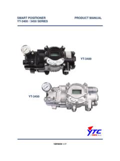
Transcription of Installation and operating instructions for the AVID ...
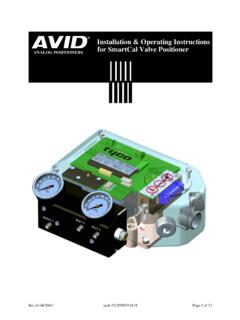
1 Contents1 Description of Principal of Operation12 Initial Mounting positioner on a Mounting Remote positioner on aRotary Wiring the Remote Sensor to thePositioner42. 4 pneumatic Electrical Enter Configure The Positioners Automatic Calibration (Quick Cal) 83. 4 Advanced Calibration (Optional) Exit Manual Override of Description of Description of Functions11-124 Trouble Preliminary Common Problems145 Specifications156 Error Codes157 Exploded Parts List16 AppendicesAProcedure to Adjust Err 3 Setting17 BProcedure to Remove Display Board & Electronic Caniste18 CProcedure to Check transducerOperation19 DGrounding Schematic20 EPneumatic Manifold Diagram21F Procedure to Reset the EEprom to factory Settings22G HART Communicator MenuFlow Chart23 Installation and operating instructions for the AVIDS martCal Intelligent Valve SmartCal Valve positioner - Figure 793 Installation & operating
2 instructions Copyright by Tyco International Flow Control reserves the right to change product designs and specifications without 83 000 922 69011 Description of SmartCal PositionerThe SmartCal Valve positioner is an electro - pneumatic servo system that continuously controlsthe position of a valve based on a 4 to 20 mA input signal. The SmartCal is an instrument thatderives its power directly from a control systems current loop. The instrument senses valveposition via a non-contact Hall effect sensor and controls valve position through a current topressure of the SmartCal can transpire by two means. Non-Hart calibration is through anon-board keypad.
3 Communication using Hart protocol allows calibration and access to on-line diagnostics via a Rosemount 275 hand-held terminal or through positioner has a local liquid crystal display which indicates valve position and set-pointin percentage open. It also indicates whether the positioner is in calibration SmartCal has the capability to monitor operation. If a failure condition occurs, an errormessage is displayed on the local liquid crystal Principal of OperationUnlike conventional positioners, the SmartCal positioner feeds back valve positionwithout the need for linkages, levers, or rotary and linear seals. Position sensing isperformed totally by non-contacting means, permitting use of advanced controlstrategies where knowledge of valve position is used in predictive and other algorithms.
4 By the integration of multiple components into a singular, cost efficientunit, microprocessor-based intelligence can now be used to implement advancedfunctions such as early warning diagnostics and fugitive emissions SmartCal positioner provides intelligence for the control valve through a microprocessor-based diagnostic system utilising the HART protocol. Accuratemeasurement of valve stem position, input signal, actuator pressure and travel timecan be recorded during normal operation, thereby providing information for controlvalve signature Position FeedbackTo provide consistently accurate performance information, all linkages, levers andconnecting rods, from the positioner to the control valve have been eliminated fromthe design.
5 Valve position sensing is performed totally by non-contacting meansbased upon characterisation of flux strength as a function of Position ControlSince valve position feedback to the SmartCal positioner is accomplished by non-contacting means, the SmartCal has the unique ability to be mounted remotely(up to a distance of 15 metres) from the device it is controlling. In the event the control valve is located in either a high vibration or extremely corrosive environment, the non-contact position feedback feature allows for isolated placement of the SmartCal Valve positioner - Figure 793 Installation & operating instructions Copyright by Tyco International Flow Control reserves the right to change product designs and specifications without Keypad/LCDThe SmartCal positioner is supplied with HART interface or a 3-button keypadinterface.
6 Both versions are furnished with a 4-digit, 12mm tall LCD, and allow forautomated calibration of the positioner . The local LCD provides a multitude of onsitediagnostic information. While the valve is being controlled by the positioner , and theerror signal is not zero, the displayed information will alternate between setpointand position as a percentage. Each value is displayed for a period of two the setpoint and valve position agree to within less than , the display willonly show position. The range of values displayed are from to resolution is in increments, however, internal calculations are maintained at higher SensorsThe SmartCal positioner has the capability to monitor its operation.
7 If anerror or failure condition occurs, it willbe displayed on the local LCD, or if thepositioner is supplied with HART interface, the error codes will be displayed on a hand held terminal or aPC maintenance station. Note: Errorcodes are denoted on a label affixed tothe LCD flip-up protective Calibration (HART Protocol)The SmartCal positioner responds toHART commands for seeking the valve closed position and assigns aninstrument signal of 4 mA to this position. The counterpart of the operation for a full open state is implemented next by setting the spanvalue. Action reversal is also configured. Additionally, provisions aremade for altering internal servo looptuning via the HART link.
8 In this manner, positioner performance maybe optimized with a wide combinationof valves and Initial SetupCondition 2:Actuator fails in a anti-clockwise direction (Turns clockwise from fail position).Spring ReturnOutput Port 2 is Port 1 is piped to turn the actuator ActingOutput Port 2 is piped to turn the actuator Port 1 is piped to turn the actuator FacesThe Front of thePositionerActuator (In Fail Position)Mounting AssemblySupplyPort 1 Port 2 Triangle Faces theFront of thePositionerActuator (In Fail Position)Mounting AssemblySupplyPort 1 Port 2 TURNSANTI-CLOCKWISE(From Fail Position)TURNS CLOCKWISE(From Fail Position) Mounting positioner on a Rotary ActuatorCondition 1:Actuator fails in a clockwise direction(Turns anti-clockwise from fail position).
9 Spring ReturnOutput Port 2 is Port 1 is piped to turn the actuator ActingOutput Port 2 is piped to turn the actuator Port 1 is piped to turn the actuator 2-1 Note:Please ensure the Tyco/Keystoneactuator is provided with the standard 16 dia x 11 AF SmartCal Valve positioner - Figure 793 Installation & operating instructions Copyright by Tyco International Flow Control reserves the right to change product designs and specifications without 2:Actuator fails in a anti-clockwise direction (Turns clockwise from failposition).Spring ReturnOutput Port 2 is Port 1 is piped to turn the actuator ActingOutput Port 2 is piped to turn the actuator Port 1 is piped to turn the actuator FacesSide With TheConduit EntryActuator (In Fail Position)Mounting AssemblyConduit EntryPositioner SensorTriangle Faces theSide With TheConduit EntryActuator (In Fail Position)MountingAssemblyConduit EntryPositioner SensorTURNSANTI-CLOCKWISE(From Fail Position)TURNS CLOCKWISE(From Fail Position) Mounting Remote positioner on a RotaryActuatorCondition 1:Actuator fails in a clockwise direction(Turns anti-clockwise from fail position).
10 Spring ReturnOutput Port 2 is Port 1 is piped to turn the actuator ActingOutput Port 2 is piped to turn the actuator Port 1 is piped to turn the actuator 2-2 NotePlease ensure the Tyco/Keystone actuator is provided with the standard 16 dia x 11 af SmartCal Valve positioner - Figure 793 Installation & operating instructions Copyright by Tyco International Flow Control reserves the right to change product designs and specifications without 2 SUPPLYJ1J4AJ4 BCALLCD1TP1J5TP2J6 TRANSDUCEROUT 1J312 3 45 6-+4-20mA87654321 Tyco reserves the right to change the contents without noticepage 5 Position Sensor(Mounted on Actuatoras Described in Section )Figure Wiring the Remote Sensor to the PositionerMount positioner at a remote location, wire the positioner sensor back to the positioner using the cable provided (See Figure 2-3).
