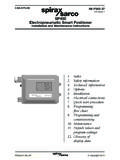
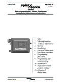
Transcription of IP8m Series Electro-Pneumatic Positioner/Smart …
1 SeriesImproved visibility of opening indicatorAllows checking of controlfrom outside bodyOpening indicator plateinside bodyExternal scale plateLCD windowInternal openingindicator plate[Option] Electro-Pneumatic Positioner/Smart positioner (Lever type/Rotary type)Passed by external organization on JISF8007 (conforms to IEC 60529) IP65 Electro-Pneumatic positioner Opening current transmission analog (4 to 20 mA DC) continuous outputSmart positioner Alarm point output function (2 points) Analog (4 to 20 mA DC) continuous outputA centralized exhaust system employs the combination of the check valve and the labyrinth effect enhancing both dustproof and waterproof (Lever type)IP8000(Lever type)IP8100(Rotary type)IP8101(Rotary type)Dustproof / WaterproofExplosion-proof constructionWith internal opening indicator plateBody with LCD windowMonitoring functionWith external scale plate (Rotary type, Bottom mounting)( smart positioner )IP8000/8100 SeriesIP8001/8101 SeriesElectro- pneumatic PositionerSmart PositionerUniversal mechanically controlled typeElectronically controlled easy-adjustmenttransmitting typeElectro- pneumatic PositionerTIIS explosion-proof construction(Exd2BT5)ATEX intrinsically safe explosion-proofconstruction (22G Ex ib2CT5/T6) smart PositionerATEX intrinsically safe explosion-proofconstruction (21G Ex ia2CT4/T5/T6 Ga)124 smart PositionerBuilt-in microcomputer and sensor allows easy remote parameter change and exampleInput value (%)Handles 2-line Input for Current EquipmentFull Output FunctionsHART Transmission FunctionControl State DisplayIntercompatible InstallationDimensions of mounting parts same as previous me-chanical IP6000/IP8000 Series Electro-Pneumatic Posi-tioner.
2 External feedback lever and fork lever-type fitting for joining actuator and positioner are therefore also the models with output functions by model selec-tion selects with alarm point output function (2 points) and analog (4 to 20 mA DC) continuous output will allow remote detection of operating transmission function can be designated by model remote monitoring and setting change of furnished with current 2-line input signal (4 to 20 mA DC) not requiring separate power , deviation, and input value are displayed (numerically) on the internal LCD, allowing visual verification of the control Saving ProductLever-type features 60% reduced air flow consump-tion compared with IP8000. Internal push button for easy setting of various parameters (Refer to parameter list) Zero point/span adjustment easier than with previous mechanical positionersParameter ListLCD window (Option)IP8001(Lever type)IP8101(Rotary type)IP8001/8101 SeriesDeviation (%)Positioning (%)NotesParameterDescriptionStandardequi ppedfunctionsPositive operation/reverse operation settingChange operation direction with regard to input signalChange to internal components, piping not possibleSplit range settingChange range of input signalPreferred zero point/span adjustment settingChange actuator stroke range with regard to input signalForced full close/full open settingTo ensure valve closure, force actuator opening to be 0% or 100% with a preferred input characteristic settingSelect from these 6 valve characteristics Linear characteristic Equality % characteristic (2 kinds) Quick open characteristic (2 kinds)
3 User preferred point setting (11 points)PID constant settingChange PID constantCalibration settingZero point/span adjustment, Auto PID constant setting, input signal display value calibration, 1 output settingSet upper/lower stroke limits for actuator from which alarm is outputAlarm 2 output settingAnalog (4 to 20 mA DC) output settingSet increase/decrease direction for 4 to 20 mA DC output with regard to actuator stroke125 IPIW1301 AWIL1 IL2 ITCP ISVFNIN-T IP[Option] Enclosure: JISF8007 IP65 (conforms to IEC 60529) Monitoring function (Opening current transmission 4 to 20 mA DC, Accessory J, JR) Explosion-proof construction/ Electro-Pneumatic positioner : TIIS explosion-proof construction (Exd @ BT5), ATEX intrinsically safe explosion-proof construction (@ 2G Ex ib @ CT5/T6)Lever typeIP8000 Rotary typeIP8100IP8000/8100 SeriesElectro- pneumatic positioner (Lever type/Rotary type)0 TypeConstruction Note 1)000IP80X14000IP81100 Pressure gaugeHow to OrderOption Note 10)ATEX directive compliance and connectionATEX Directive IntrinsicallySafe Explosion proofStandardCE markingConnectionNote 1) For construction (with terminal box), the ambient and fluid temper-atures are as follows: Exd2BT5 20 to 60 C Non-explosion proof (non hazardous Iocations only) 20 to 80 CThe positioner body is EXd2BT5 2) If two or more accessories are required, the part numbers should be made according to alphabetical order.
4 (ex. IP8100-010-AG)Note 3) A is applied to approx 90cm3-capacity actuator. B is applied to approx 180cm3-capacity 4) Fork lever-type fitting MX (Connection thread: M6 x 1) for 5) Fork lever-type fitting SX (Connection thread: M6 x 1) for 6) Standard lever is not 7) It is to be used together with A or B when tending to overshoot by the use of A or B . It is mounted to the body as a replacement of the standard compensa-tion 8) For side mounting, select a model with internal opening indicator plate (IP8100-0ll-l-l-X318 for standard type, X14-W for ATEX intrinsical-ly safe explosion-proof type).Note 9) Symbol J/JR is with terminal box, non-explosion proof specification. Se-lect 1 for Construction. Positive operation signifies clockwise rotational direction by the main actuator shaft when positioner cover is viewed from the 10) Combination of L and W is not Note 2)000 Electro-Pneumatic lever type100 Electro-Pneumatic rotary MPaSymbolAirElectricApplicable modelIP8m00-0m0 IP8m00-0m1 NilRc1/4G1/2 VVMRc1/4M20 x NRc1/41/2 NPTV 11/4 NPTG1/2VV21/4 NPTM20 x 31/4 NPT1/2 NPTV 4G1/4G1/2VV5G1/4M20 x 6G1/41/2 NPTV Nil QCE marked product01No terminal boxWith terminal box(Exsd2BT5) TIIS (Japan)explosion-proof itemSymbolOptionApplicable modelIP8000-X14 IP8100-X14 Nil VVLLow temperature ( 40 to 60 C)VVWWith internal opening indicator plate VX14 ATEX directive category 2 Intrinsically safe explosion-proof itemAir connection port: 1/4 NPTC onduit connection port.
5 M20 x blue cable glandSymbolAccessoriesApplicable modelIP8000 IP8100 NilNone (Standard)V VA Output restriction with pilot valve Note 3)V VB Output restriction with pilot valve Note 3)V VCFork lever-type fitting M Note 4) VDFork lever-type fitting S Note 5) VEFor stroke 35 to 100 mm with lever unit Note 6)V FFor stroke 50 to 140 mm with lever unit Note 6)V GCompensation spring (A) Note 7)V VHWith external scale plate Note 8) VJWith opening current transmission (4 to 20 mA DC)/Positive operation Note 9) VJRWith opening current transmission (4 to 20 mA DC))/Reverse operation Note 9) VMPaMPaPOSITIONERMPaMPaPOSITIONER126[Opt ion] Auto calibration HART transmission function Enclosure: JISF8007 IP65(conforms to IEC 60529) Monitoring function Explosion-proof construction/ATEX intrinsically safe explosion-proof construction (@ 1G Ex ia @ CT4/T5/T6 Ga)IP8001/8101 SeriesSmart positioner (Lever type/Rotary type)Lever typeIP8001 Rotary typeIP8101 ATEX Directive IntrinsicallySafe Explosion proofStandard0 3 0001IP8520 3 4001IP8 How to OrderATEX directive complianceSpecificationsConnectionNote) When the symbol is M, 2, or 5 for 52- ATEX directive items, a blue cable gland is included with the electrical markingATEX temperatureAccessories Note 1)TypePressure gaugeSpecificationsNote 1) If two or more accessories are required, the part numbers should be given in alphabetical order.
6 (ex. IP8101-010-CH)Note 2) Standard lever is not 3) For side mounting, select -W and check the control position by viewing the LCD display modelIP8001 MPaV MPaV MPaV V0 Basic type2 With output function {Analog (4 to 20 mA DC) output + Alarm output x 2}3 With HART transmission function001 smart lever type101 smart rotary typeSymbolAccessoriesApplicable modelIP8001 IP8101 NilNone (Standard)V VCFork lever-type fitting M VDFork lever-type fitting S VEFor stroke 35 to 100 mmwith lever unit Note 2)V FFor stroke 50 to 140 mmwith lever unit Note 2)V HWith external scale plate Note 3) VWBody with LCD windowV VSymbolATEX temperatureApplicable modelIP8001 IP8101 NilT4V VT6T5/T6V VNil QCE marked productSymbolAirElectricNilRc1/4G1/2M Note)Rc1/4M20 x Note)1/4 NPTM20 x Note)G1/4M20 x safe explosion proof (ATEX) + output function + HART transmission function52 ATEX directive category 1 Intrinsically safe explosion-proof item127 IPIW1301 AWIL1 IL2 ITCP ISVFNIN-T IPSpecifications Note 1)Optional SpecificationsNote 1) Indicates analog output accuracy with respect to actuator angle.
7 Note 2) Indicates analog output accuracy with respect to LCD display position value (P value).Note 1) Specification values are given at normal temperature (20 C).Note 2) 1/2 Split range (Standard). For operation with 1/2 split range, the linearity and hysteresis should be 1% higher than the above 3) Stroke adjustment: 0 to 60 , 0 to 100 Note 4) Characteristics relating to accuracy differ depending on combination with other constituent loop equipment, such as positioners and 5) While there is no output changes due to pressure fluctuations, when the pres-sure supply setting is changed following calibration, once again adjust balance current and perform calibration. Note 6) Air consumption is due to exhaust from nozzle. And (ANR) indicates JIS B0120 standard 7) Model selection required for explosion proof construction and HART 8) For IP66 compliant products, refer to pages 142 to 9) Thread type can be specified by model (Non-explosion proof)IP8m01-0m2 (Non-explosion proof)52-IP8m01-0m4 Electro-Pneumatic PositionerSmart PositionerAnalogoutputWiring2-lineOutput signal4 to 20 mA DCPower supply voltage12 to 35 V DC10 to 28 V DCLoad resistance(Power supply voltage 12 V) 20 mA DC or less0 to 750 WAccuracy 2% or less Note 1) or less Note 2)HysteresisWithin 1% Alarmoutput 1, 2 Wiring 2-lineApplicable standards DIN19234/NAMUR StandardPower supply voltage 10 to 28 V DC5 to 28 V DCLoad resistance 10 to 40 mA DC(Constant current output)Alarm ON R = 350 W 10% mA DCAlarm OFF (Leakage current)
8 MA DC or less mA DCResponse time 50 msec or lessTypeItemIP8000IP8100IP8001IP8101 Electro-Pneumatic PositionerSmart PositionerLever type lever feedbackRotary type cam feedbackLever typeRotary typeSingle actionDouble actionSingle actionDouble actionSingle action / Double actionInput current4 to 20 mA DC (Standard) Note 2)Min. operating current mA DC or moreIntra-terminal voltage 12 V DC (equivalent to 600 W input resistance, at 20 mA DC)Max. supplied power 1 W (Imax: 100 mA DC, Vmax: 28 V DC)Input resistance235 15 W (4 to 20 mA DC) Supply air to to MPaStandard stroke10 to 85 mm (Allowable deflection angle 10 to 30 )60 to 100 Note 3)10 to 85 mm (Allowable deflection angle 10 to 30 )60 to 100 Note 3)Sensitivity Note 4)Within Note 4)Within 1% 2% 1% Note 4)Within 1% Note 4)Within of temperatureWithin CWithin CSupply pressure fluctuationWithin MPa Note 5)Output flow Note 6)80 L/min (ANR) or more (SUP = MPa) 200 L/min (ANR) or more (SUP = MPa)Air consumption Note 6)5 L/min (ANR) or less (SUP = MPa)11 L/min (ANR) or less (SUP = MPa)2 L/min (ANR) or less (SUP = MPa)4 L/min (ANR) or less (SUP = MPa)11 L/min (ANR) or less(SUP = MPa)Ambient and fluid temperatureGeneral structure: 20 to 80 CTIIS explosion-proof: 20 to 60 CATEX intrinsically safe explosion-proof.
9 20 to 80 C (T5) 20 to 60 C (T6) 40 to 60 C (T6)/-L type low-temperature specificationATEX intrinsically safe explosion-proof 20 to 80 C (T4/T5) 20 to 60 C (T6)Explosion proof construction Note 7)TIIS explosion-proof construction (Exd2BT5)ATEX intrinsically safe explosion-proof construction (22G Ex ib2CT5/T6)ATEX intrinsically safe explosion-proof construction(21G Ex ia2CT4/T5/T6 Ga)ATEX intrinsically safe explosion-proofparameter (current circuit)Ui 28 V, Ii 125 mA, Pi WCi 0 nF, Li 0 mHUi 28 V, Ii 100 mA, Pi W Ci nF, Li mHExterior covering enclosure Note 8)JISF8007, IP65 (conforms to IEC )Transmission method Note 7) HART transmissionAir connection port Note 9)Rc 1/4 female thread, NPT 1/4 female thread, G 1/4 female threadElectrical connection port Note 9)G 1/2 female thread, M20 x female thread, NPT 1/2 female threadMaterial/coatingAluminum diecast body/baking finish with denatured epoxy kg (Without terminal box) kg (With terminal box) kg128IP8 Series63 (S/SX type: 39)L1=101(S/SX type: 77)Actuator main shaftM8 x M6 x 139(M/MX type: 63)L2=31(M/MX type: 55)Actuator main shaftM8 x M6 x 1 Side mounting with the fork lever assembly M/MXRear mounting with the fork lever assembly S/SXPilot valve with output restriction (IP8000/8100)Accessory/OptionIn general, mounting on a small-size actuator may cause hunting.
10 For prevention, a pilot valve with a built-in output restriction is available. The restriction is feedback lever (IP8000/8001)Different feedback levers are available dependent upon valve strokes. Order according to the valve P5 RestrictorOrifice sizeRestrictorRestrictorRestrictor mounting diagramPilot valve bottom viewFork lever-type fittings (IP8100/8101)2 kinds of rotary type IP8100/8101 fork lever-type fittings, that differ by installation dimensions dependent on bracket installation method, and 2 kinds of installation portion thread sizes, are installing on the side surface, using fork lever assembly M provides interchangeability with the installation dimensions of SMC IP610 positioner . When installing on the rear surface, using fork lever assembly S also provides interchangeability with the installation dimensions of SMC IP610 connector (Non-explosion proof specification)Optional cable connectors are available for different cable sizes.