Example: bankruptcy
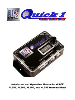
Installation and Operation Manual for 4L60E, 4L65E, 4L70E ...
Step 3: Throttle Position Sensor Attach the 3 Throttle Position wires from the Quick 1 to the Throttle Position Sensor. Pin 16 Black is dedicated ground. Pin 11 Orange is +5v reference feed. Pin 3 Dark Green is the position sensor signal. See the …
Tags:
Information
Domain:
Source:
Link to this page:
Documents from same domain
Installation and Operation Manual for 4L60E, 4L65E, 4L70E ...
www.usshift.com4 PREPARATION 4L80E Transmission: Pre-1993 4L80E transmissions use a different internal wiring harness and pass-through connector. This early harness has a problem with leaking fluid at the

Installation and Operation Manual for the Ford ... - US Shift
www.usshift.com2nd Gear” options in the FLEX-SHIFT tab. If the transmission starts in second while still learning, it will result in erroneous data and hard shifts. o Use Softer Shifts If you plan on having a soft shift and firm shift calibration, it’s best to have the controller learn using softer shifts. This …
Related documents
NISSAN REVISED TPS ADJUSTMENT PROCEDURE
lyberty.com8. Tighten the TPS retaining bolts, then repeat steps 5 and 6 two or three times to check the new adjustment. 9. Re-connect the harness connector to the CTPS portion of the (TPS). Reset throttle position sensor idle position memory. NOTE: Failure to reset the TPS idle position memory may result in the idle speed staying higher than specification.

ELECTRONIC ENGINE CONTROLLER - Chrysler
starparts.chrysler.comsensor readings. • Auto-shutdown (ASD) relay: Corroded wires or faulty relay. • Manifold Absolute Pressure (MAP) sensor and Throttle Position Sensor (TPS) voltages: Check voltages over the entire range, not just the extremes. Verify minimum TPS voltage. • Minimum air flow: Check for air leaks or airflow obstruction.

550-870, 550-870K, 550-871, 550-871K, 550-872, & 550-872K ...
documents.holley.comJun 09, 2020 · Pressure (MAP) sensor, Throttle Position Sensor (TPS), Manifold Air Temp Sensor (MAT), and an Idle Air Control Valve (IAC) 5 Air Cleaner Gasket 1 9 3.5” Touch Screen Controller 1 553-115 Includes harness to connect directly to CAN connector 10 Output Harness 1 558-491 Shutdown, Electric Fan #1 Output, and/or
Mechanic Study Guides - Michigan
www.michigan.govTPS (throttle position sensor) Operation . General Diagnosis - 18% . Harsh engagement . Governor malfunctions . Fluid diagnosis . Glazed band diagnosis . Fluid leak diagnosis . Pressure testing . Spool valve diagnosis . Burned clutch diagnosis . Fluid loss diagnosis . Drivability Diagnosis - 28% .

Formula Student Rules 2022
formulastudent.deTPS Throttle Position Sensor TS Tractive System TSAC Tractive System Accumulator Con-tainer TSAL Tractive System Active Light TSMP Tractive System Measuring point TSMS Tractive System Master Switch USS Unsafe Stop VSV Vehicle Status Video Formula Student Rules 2022 Version: 0.97of 130

625 STREET DEMON™ - Holley
documents.holley.comJan 08, 2016 · throttle position sensor signal to operate properly, Demon has you covered. Part # 1951 Street Demon TPS kit is designed to bolt directly to your new Street Demon™ carburetor to provide the needed TPS signal to an electronic transmission. Consult the installation manual for the 1951 Street Demon TPS kit for installation and adjustment ...

Harley Diagnostic Codes
www.thunder-max.com39. P2176 EFI Closed Position Not Learned 40. P1514 Air Flow Fault 41. P2105 EFI Forced engine shutdown 42. P1501 Jiffy Stand Sensor Low 43. P1502 Jiffy Stand Sensor High 44. P0572 Brake Switch Low 45. P0117 ET Sensor Low 46. P0118 ET Sensor High 47. P0112I AT Voltage Low 48. P0113I AT Voltage Open/High 49.

Microsquirt Hardware Manual - EFI Source
www.efisource.comMicrosquirt Hardware Manual Megasquirt-2 Product Range MS2/Extra 3.3.x Dated: 2015-03-14 Hardware manual covering specific wiring and configuration of your Microsquirt ECU.