Transcription of Installation and Service Guide - H2O Distributors
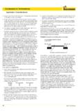
1 Installation and Service Guide Reverse Osmosis System with Quick-Connect Fittings USRO4-50-qc-38-USA / USRO4-60-qc-38-USA / USRO4-100-QC-38-USA. USRO5-50-qc-38-USA / USRO5-60-qc-38-USA / USRO5-100-QC-38-USA. Please read this manual carefully before attempting Installation System and Faucet Diagram 1 Insert tube How to make a Quick-Connect Connection 1. Fitting grips before it seals. Ensure tube is pushed into the tube stop. 2. Push the tube into the fitting, to the tube stop. The collet (gripper) has 2 Push up to tube stop stainless steel teeth which hold the tube firmly in position while the O-ring provides a permanent leak-proof seal. 3. Pull on the tube to check that it is secure. It is a good practice to test the system prior to leaving site and/or before use.
2 3 Pull to check secure 4. To disconnect, ensure the system is depressurized before removing the tube. Push in collet squarely against face of fitting. With the collet held in this position, the tube can be removed. The fitting can then be re-used. 4 Disconnecting Note: See exploded diagram (on last page of this manual) regarding locking clips and plugs. Your Reverse Osmosis (RO) System has been tested and gently push in the tubing until it will not go any further. to ensure it will operate correctly. The following periodic To ensure that your tubing has made a snug fit, pull back maintenance is recommended so your system will provide gently on the tubing; it should catch. Always check for leaks years of trouble-free Service : to ensure a watertight connection.
3 (see Figure 1). Prefilters (sediment) Once per year Tools Prefilter (carbon block(s)) Once per year The following tools may be necessary, depending on each RO Membrane Usually Every 2 years particular Installation : Postfilter (carbon) Once per year variable speed electric drill (2,500 RPM is best for System Components stainless steel); , & metal cutting bits , & Concrete drill bits (for porcelain sinks). The following components make up your reverse osmosis Phillips head screw driver system: 6 adjustable wrench Teflon tape & Plastic tubing cutter Prefilter #1 (sediment) Melt Blown Polypropylene filter Hammer & Center punch removes larger particles such as dirt, rust & sediment. System Location Prefilter #2 (& 3 if applicable) 10 Micron Carbon Block removes chlorine and chemical contaminants in the feed Your RO system may be installed under a sink or in a water and protects the RO membrane.
4 Basement. Do not install unit where it would be exposed to freezing temperatures. Connecting to an icemaker or other Reverse Osmosis Membrane Thin Film Composite remote location can also be considered if a connection can Membranes reduces dissolved minerals, metals, and salts. be made without using more than 12 of tubing, otherwise In this process, harmful compounds are separated by a delivery pump may be needed. Farther runs can be the membrane from the water, and the contaminants are attempted and a pump can be added later only if needed. flushed to the drain. Guidelines for component placement are as follows: A coconut shell activated carbon postfilter is provided for a final polish and to remove tastes, odors and to provide Faucet should be placed on, or near the sink where great tasting water.
5 Drinking/cooking water is normally required. A 2 flat surface is required to mount faucet if an existing hole is not The RO module is the main component and holds the available. The thickness of the mounting surface should prefilters and membrane, and postfilter. A bracket is not exceed 1 or a faucet extension (not supplied) will be provided so they can be mounted under the sink or in a needed. basement. Bladder Tank maybe placed where it is convenient, within Bladder tank holds RO purified water, ready to use. ten feet of the faucet. Under the sink or in a nearby cabinet or in basement rafters are excellent choices. Full tanks can Automatic shut-off valve closes when the storage tank is weigh more than thirty pounds; so make sure any shelving full and shuts off the water supply to conserve water.
6 The used is secure. Bladder tank can be placed on its side or valve activates when the tank pressure is 2/3 of the feed upright. pressure. RO Unit may be mounted on either side of the sink, The RO Faucet is used to dispense purified water when in the back of a cabinet, or in the basement. Mounting you want it. the unit on the left or the right side of the cabinet under the sink provides for easier access to the unit for future Feed water saddle valve connects to the cold water line maintenance. to supply water to the RO system. A Faucet Adaptor and Ball Valve Shut-Off are used Wastewater saddle valve connects to the drain to remove to supply feed water to the RO unit and provide an easy reject water from the RO system. ability to shut off the water supply when servicing the unit.
7 These are shown in Figure 2. Tubing connects all RO components. A Drain Saddle is used to make a waste water connection Quick-Connect fittings are used for necessary tubing with your drain under the sink. This is designed to fit connections. These fittings connect by pushing the tube around a standard 1-1/2 OD drainpipe. The drain saddle into the fitting past a slight resistance until the tube bottoms valve should always be installed before (above) the p-trap out in the fitting. Simply make a clean cut in your tubing and on the vertical or horizontal tailpiece. Do not install the drain saddle near a garbage disposal to avoid clogging the 2. Drill the pilot hole drain line with debris. 3. Continue to enlarge hole with larger size drill bit until it is 1/2.
8 Unit preparation 4. Clean up sharp edges Open shipping carton, remove components and check that Note: Air Gap Faucets are required by some all parts are present. municipalities. These faucets require a 1 hole in the sink rather than the hole required by the standard faucet Installation Steps included with the RO system. To make a 1 hole to accommodate an air gap faucet requires special tools such as a chassis punch (stainless steel) or a Relton cutter All plumbing must be completed in accordance with state (porcelain) if a large enough hole is not already available. and local plumbing codes. Some municipalities may require Ask your local dealer for more information. Installation by a liscensed plumber. Check your local plumbing codes for more information.
9 1. Faucet Installation (See Figure 1). If the sink has a sprayer, it may be disconnected for faucet Installation . A pipe cap or plug will be necessary to seal the sprayer connection or sprayer can be left connected under the sink. When making the faucet hole (if a sprayer or other existing hole in not being used), check below the sink to make sure the drill will not interfere with anything under the sink. A 2 . flat surface on the sink is required for mounting the faucet. The faucet should be positioned so it flows into the sink and the spout should be allowed to swivel freely for convenience. If an existing hole is being used to mount the faucet, proceed to Step 2. Installation procedures for Porcelain, 2. Mounting the Faucet Enamel, Ceramic on Metal, or Cast Iron: Disassemble hardware from the treaded shank.
10 Chrome Precautions must be taken to penetrate the porcelain base plates and rubber washers slide up the shank to the through to the metal base and prevent chipping or faucet body. scratching. Feed threaded shank through the sink hole and orient the Procedures: faucet. From below sink, slide lock washer and hex nut over threaded shank and tighten with a wrench. 1. Mark the center with center punch for the 1/4 pilot hole. Note: It is best to have someone hold the faucet from 2. Carefully drill pilot hole with masonry pit through above the sink to keep it from moving out of place. If this is porcelain and stop when metal shows. (Use light not possible then tighten the hex nut until it is just slightly pressure and slow speed) less than completely tight.
