Transcription of Eaton STC Connectors Catalog
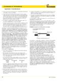
1 Eaton STC Connectors CatalogEATON STC Catalog E-MEFI-MC003-E2 April 20162 Table of ContentsMarkets, Applications, and Equipment ..3 How STC Works ..4 Understanding STC Components ..5 How to Order STC Connectors ..6 Performance Characteristics ..7 STC Test Regimen ..8 What You Should Know About STC Connectors ..9 Installation and Disconnection of STC Connection ..10 Service Instructions for STC Connectors ..11 Assembly Method and Verification ..12 STC Insertion Length and Connection Dimensions ..13 Global Crimp Hose Nipples ..14 TTC Crimp Fittings ..17 TTC12 Crimp Fittings ..18 Crimp Nipples for FC699 Hose ..19 Crimp Nipples for Teflon Hose ..20 OTC Crimp Fittings ..21 Crimp Fittings for SAE 100R5 Hose ..22 STC Socketless Fittings ..23 Female STC Cap and Male STC Plug ..24 Brazed Male and Female STC on High Pressure Carbon Steel Tubing ..25 Braze-On Male and Female Spud for Tubes ..26 Formed Male STC Tubing (Carbon Steel).
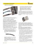
2 27 Adapters ..28 Press Fit Adapters ..39 Press Fit Adapter Installation Instructions ..41 Direct Port STC Connections ..42 Female Ring Insertion Tools ..44 Accessories and Sales Tools ..48* Teflon is a registered trademark of DuPont used under license by Hydraulics warranty policy is located at STC Catalog E-MEFI-MC003-E2 April 2016 Markets, Applications, and EquipmentApplications Hydraulic Power Steering Auxiliary Hydraulics Power Brakes Turbochargers Fuel Injection Systems Hydraulic Work Circuits Air Conditioning, Refrigeration and Truck and Bus Refrigerant Supply Lines Compressor Discharge Power Steering Oil Cooler Pneumatic Brakes Air Supply Lines Cooling Transmission Oil Coolers Heat ExchangersEquipment Tractors Ag and Utility Loaders Backhoe and Skid-Steer Engines Truck, Marine, Construction Snow plows Trucks Lift.
3 Utility Bucket Crawlers Compressors Trailers Reel and Deck Mowers Asphalt and Concrete Pavers Trenchers Lift Platforms Hydraulic AttachmentsEATON STC Catalog E-MEFI-MC003-E2 April 20164 STC Assembly ActionAs the STC tool is inserted behind the release sleeve, the steel insert pushes the latching ring forward into a groove in the female half I .D ., allowing the two halves to be pulled apart . The thickness of the tool moves the sleeve forward far enough to make the discon-nection, so prying sideways with the tool is unnecessary .STC Disassembly ActionThe male connector is insert-ed into the female connector . The male shoulder spreads the latch ring open .When the latch ring is in its open position, the male shoul-der can slide past the latch ring .The male and female are locked into place . As fluid pressure is applied, the latch ring is wedged between the male shoulder and the female angle . Warning: Note: Do not use the disconnect tool to pry on the parts.
4 Prying can result in damage . Insert the tool straight into the connection .The proper connection and discon-nection of STC parts is outlined in on page 12 .Note: Always remember to verify that your STC connection has been made successfully by pulling on the STC WorksDo NOT disconnect STC connection when under pressure. Failure to observe the foregoing may result in property damage or personal STC Catalog E-MEFI-MC003-E2 April 2016 Male STC Connector555* -04 size only available with polyurethane seal material ** -04 size does not include a back-up ring156 Female STC Connector234 Understanding STC Components1. Disconnecting Tool Used for disconnecting the two halves of an STC connection.
5 2. O-Ring* Buna-N (standard), fluo-rocarbon, EPR, or HNBR materials provide leak-proof sealing for hydrau-lic, air, and refrigeration applications .3. Back-Up Ring** PTFE back-up ring pro-vides resistance to high pressure o-ring extrusion under critical impulsing applications .4. Latch Ring Stainless steel latch ring connects the two halves while under full pressure, impulsing applications .5. Latch Ring A steel insert molded to an elastomeric dustboot provides both the mecha-nism for disconnecting the mating STC halves and protection against contamination when the two halves are connected .6. Latch Verification Ring The male release sleeve covers the red o-ring on the female when the male and the female halves are properly connected . Eaton STC Catalog E-MEFI-MC003-E2 April 20166 STC Adapters: First, state the base part number, thread size, then the nominal STC interface size .(For adapters add a 0 prefix to interface and port thread sizes 6 and 8.)
6 List o-ring material designa-tion suffix; omit the S suffix if ordering alternate o-ring materials .Buna-N (nitrile) is the STC standard; no suffix is needed for standard Buna-N .EPR (Ethylene Propylene Rubber) = -212 Fluoroelastomer = -213 Neoprene = -352 HNBR = -461 Polyurethane = -523 Example: FF3042-0606-213 STC Global Hose Crimp Hose NippIes: Part numbers collapse to the shortest possible number of digits . It is assumed that a global fitting has a straight configuration unless a code is added to designate other-wise .(Steel is the only available material .) A=45 B=90 Standard or Medium Drop C=90 Long DropStandard Crimp Hose Fittings: Fittings are ordered as component parts . First, state the base part number, then the nominal STC interface size, then the hose size . Application Fluid Seal Elastomer Specification Temperature RangeBuna-N/Nitrile None -40 F to +250 F (-40 C to +121 C) EPR None -65 F to +300 F (Ethylene Propylene Rubber) (-55 C to +150 C)Flourocarbon MIL-R-25897 -15 F to +400 F (-25 C to +205 C)Neoprene None -65 F to +300 F (-55 C to +150 C)HNBR None -40 F to +300 F (Hydrogenated Nitrile Rubber) (-40 C to +150 C)Polyurethane* -40 F to +250 F (-40 C to +121 C)Seal Elastomer DataNote: Ambient temperature range is -40 F to +300 F (-40 C to +150 C).
7 * For -04 STC only. STC size -04 comes standard with Buna-N (nitrile) o-ring on port connector ends. FF3042-06 06 SBase Part #Port Thread SizeNominal STC Interface Size*Material Designation Suffix (S=Carbon Steel, the only approved material) FJ4828-06 06 SBase Part #Nominal STC Interface SizeNominal Hose SizeMaterial Designation Suffix S=Zinc Plated Carbon Steel (currently only approved fit ting material) 1S 12 MC 12 Global Two Piece Part #Nominal STC Interface Size**End Connection CodeMC=Male STC in straight configurationConnecting End Configuration Code How to Order STC Connectors ** When ordering interface sizes 4, 6 or 8 or hose sizes 3, 4, 5, 6, or 8, the part number requires only single STC Catalog E-MEFI-MC003-E2 April 2016 Performance CharacteristicsDesign Features Positive round-wire style latching mechanism Swivels for installation (in absence of pressure) Low profile.
8 Compact design Elastomeric o-ring seal available in many materials Capable of direct porting into valve blocks or manifolds Dual purpose dust seal/release sleeve Simple stamped release tool for disconnecting Benefits Fast reliable one-hand connections requiring no assembly tools Eliminates cross-thread-ing, over or undertorquing, and hose twisting Installs easily in confined areas Virtually zero leak performance per SAE J1176 Direct porting eliminates adapters to maximize cost savings Resists external contamination Allows easy disconnection with release tool Operating CharacteristicsInterface Maximum Minimum Size Operating Pressure Burst Pressure Vacuum psi bar psi bar 1/4 6,000 414 24,000 1,656 28 711 3/8 5,000 345 20,000 1,380 28 7111/2 4,250 295 17,000 1,175 28 7115/8 4,000 275 16,000 1,100 28 7113/4 4,000 275 16,000 1,100 28 7111 4,000 275 16,000 1.
9 100 28 711 Technology Comparison Threaded Fittings STC FittingsAssembly tools required Torque sensitive Limited reusability Virtually zero leakage Fast, reliable connections Ease of installation in confined areas improved ergonomics Ease of orienting hose ends Compact design, install and remove in limited access areas Eaton STC Catalog E-MEFI-MC003-E2 April 20168 STC Test Regimen One million cycle impulse test in excess of 133% of DIN2ST operating pressures with side load Testing for fatigue of connection Square wave fluid impulse with side load Virtually zero leakage performance criteria per SAE J1176 Burst pressures exceed 4 times DIN2ST operating pressures Proves connection reliability at high pressures 28 Inches Hg Vacuum Product tested at seal max.
10 & min temperatures Same product is then tested to twice the maximum operating pressure Virtually zero leakage performance criteria per SAE J1176 Exceeds 96 hour salt spray Functional & corrosion resistance test Per ASTM B117 Connect/Disconnect (250 Times) After 250 connects/ disconnects, adapters leak tested at twice maximum operating pressure Virtually zero leakage performance criteria per SAE J1176 Proves connection reliability and release sleeve integrityProduct Qualification Testing Vibration (5-500 Hz) Tested full vibration range for connector wear Testing capability simulates applicationAdditional Application Testing Extreme temperature test (-40 to +300 F) Covers full range of applications Dust box and seal integrity testing 48 hr, 4G vibration test in presence of fine, airborne dust particles (U.)