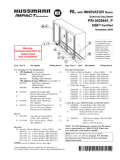
Transcription of Installation and Service Manual - Hussmann
1 ONOFFSHIFTUPPERSHIFTLOWERINSDELHELPESCEN TSPACE#12 345 67908AB CDE FGHI JKL M NOP QRSTUVW Store Equipment Data Log OptionsCom 2 19200 Alt-X Exit Alt-F3 CloseNov 08 16 : 50 : 32 Installation andService Manual andP/N 385841 CJanuary 15, 1999 Table of ContentsInstallationOverview .. 1-1 Shipping Damage .. 1-1On Site Damage Control .. 1-1 Dimensions and Weights .. 1-1 Field Supplied and Installed Water Components .. 1-1 Accessibility .. 1-2 Panel Removal ..1-2 Horizontal Units Top Removal .. 1-3 Rigging and Hoisting .. 1-4 Vibration Pads .. 1-4 Vertical Protocol Plan Views .. 1-5 Typical Piping and Electrical Hookup .. 1-6 Horizontal Protocol Plan Views .. 1-7 Typical Piping and Electrical Hookup .. 1-8 Vertical Air Cooled Protocol (Remote Condenser)Plan Views.
2 1-9 Typical Piping and Electrical Hookup .. 1-10 Horizontal Air Cooled Protocol (Remote Condenser)Plan Views .. 1-11 Typical Piping and Electrical Hookup .. 1-12 Proto-Aire Plan Views .. 1-13 Typical Piping and Electrical Hookup .. 1-14 PROTOCOL P/N 365841 Ciii990115 IMPORTANTKEEP IN STORE FOR FUTURE REFERENCEQ uality that sets industry standardsHussmann Refrigeration Systems12999 St. Charles Rock Road Bridgeton, MO 63044-2483 USA (314) 291-2000 FAX (314) 298-64852700 Crestridge Court Suwanee, GA 30024 USA (770) 921-9410 FAX (770) 381-0615 Table of Contents(Continued)Refrigeration PipingOverview ..2-1 Refrigerant Line Piping ..2-1 Refrigeration Cycle ..2-2 Basic Protocol ..2-2 Protocol with 3-Pipe Gas Defrost ..2-3 Protocol with Reverse Cycle Defrost.
3 2-4 Protocol with Heat Reclaim .. 2-5 Protocol with Satellite or Split Suction .. 2-6 Protocol with Remote Air Cooled Condenser .. 2-7 Basic Proto-Aire .. 2-8 Oil Cycle .. 2-9 Protocol Oil Return System .. 2-9 Liquid Injection .. 2-10 Field Piping .. 2-10 Water Loop PipingOverview .. 3-1 Water Loop Guidelines .. 3-1 Pipe Connections .. 3-1 Isolation Valves .. 3-1 Strainers .. 3-1 Air Vent Valves .. 3-1 Tie-In to Supply Headers .. 3-1 Pipe Supports .. 3-2 Exposure to Direct Sunlight .. 3-2 Leak Checking .. 3-2 Cleaning and Flushing .. 3-2 Filling .. 3-2 Reverse Cycle Gas Defrost .. 3-2 Balance Valve Adjustment .. 3-2 Presetting the Flow Control (Balancing) Valve .. 3-3 Balancing Water Loop for Reverse Return Piping .. 3-3 Balancing Water Loop for Direct Return Piping.
4 3-3 Balancing the Water Flow for Each Protocol .. 3-3 Balancing the System for Piping Head Loss .. 3-4 Instruction for Presetting Degree of Closure .. 3-5 ContentsivPROTOCOL Hussmann CORPORATION BRIDGETON, MO 63044-2483 USA990115 Table of Contents(Continued)ElectricalField Wiring .. 4-1 Panel Voltages .. 4-2 Alarm LED s .. 4-2 Wiring Legend ..4-3 Typical Wiring208V; 2, 3 or 4 Compressors .. 4-5460V; 2, 3, 4, 5 or 6 Compressors .. 4-6208V; 5 or 6 Compressors .. 4-7 Proto-Aire ; 460V; 2, 3, or 4 Compressors .. 4-8 Proto-Aire ; 575V; 2, 3, or 4 Compressors .. 4-9 Terminal Connections .. 4-10120V Circuit Logic .. 4-1024V Circuits ..4-10 Electronic Oil Level Control .. 4-10 Satellite Cycle Control Relay .. 4-10 Typical Oil Control Wiring Diagram - Protocol .. 4-11 Typical Oil Control Wiring Diagram - Proto-Aire.
5 4-12 Typical Liquid Injection Wiring Diagram .. 4-13 Single Defrost Schedule .. 4-13 Multiple Defrost Schedules .. 4-16 Lighting Control .. 4-20 Unit Cooler Fan Wiring .. 4-20 POWERLINK Operation .. 4-21 Wiring In-Store Alarm and Auto Dialer .. 4-22 StartupStartup .. 5-1 Oil Charge .. 5-3 Electronic Oil Level 5-5 Auxiliary Sensors .. 5-5 Reverse Cycle Gas Defrost .. 5-63-Pipe Gas Defrost .. 5-7 Electric Defrost .. 5-8 Offtime Defrost .. 5-10 Sensor ApplicationsP1 .. 5-11P2 .. 5-11T1 .. 5-12T2 .. 5-13T3 / P3 .. 5-13 Programming OptionalIn-Store Alarm and Auto Dialer .. 5-14 PROTOCOL P/N 365841Cv990115 Hussmann CORPORATION BRIDGETON, MO 63044-2483 USAT able of Contents(Continued)Troubleshooting GuideElectrical Questions .. 6-1 Troubleshooting Alarms.
6 6-6 Protocol Technical Facts Bulletins .. 6-11 Service and MaintenanceService .. 7-1 Recommended Maintenance .. 7-2 Sample Maintenance Checklist .. 7-3 Blank Maintenance Checklist .. 7-4 WarrantyContentsviPROTOCOL Hussmann CORPORATION BRIDGETON, MO 63044-2483 USA990115 Field Fabricated Headers areNOT REQUIREDfor Protocol InstallationsOVERVIEWThis section is limited to the information neededto set the Protocol Unit. Auxiliary equipmentinformation is found in the sections devoted tothem or in the manuals accompanying information is contained in Protocol Planning Data; the HUSSNET Manual ; theHand Held Device Manual ; and the PumpingStation Planning Data, Service and DAMAGEAll equipment should be thoroughly examined forshipping damage before and while equipment has been carefully inspected at ourfactory, and the carrier has assumed responsibilityfor safe arrival.
7 If damaged, either apparent orconcealed, claim must be made to the Loss or DamageIf there is an obvious loss or damage, it must benoted on the freight bill or express receipt andsigned by the carrier's agent; otherwise, carriermay refuse claim. The carrier will supply thenecessary claim Loss or DamageWhen loss or damage is not apparent until afterequipment is uncrated, a claim for concealeddamage is made. Upon discovering damage,make request in writing to carrier for inspectionwithin 15 days and retain all packing. Thecarrier will supply inspection report andrequired claim SITE DAMAGE CONTROLThe Protocol is shipped on skids with panelsinstalled. Remove panels to access lifting pointson frame. Do not attempt to move the unit fromthe skids without first removing the AND WEIGHTSV erticalLHDW eightNomenclature(in.)
8 (in.) (in.)(lb) 80 80 (in.) (in.) (in.)(lb)19FR8332 *9632 32 *Oversized Control PanelProto-Aire LHDW eightNomenclature(in.) (in.) (in.)(lb)All128 422800 Receiver capacities are based on 80% liquidfill at 105 deg lbHorizontal72 lbProto-Aire 72 lbFIELD SUPPLIED AND INSTALLEDWATER COMPONENTSThe Protocol comes equipped with a flowcontrol/shutoff valve for servicing the plate heatexchanger. All other water loop componentsmust be field supplied and installed. A 16-20mesh strainer (1 mm) is required immediatelyupstream of each Protocol .P/N 365841C1 - 1 PROTOCOL 990115 Hussmann CORPORATION BRIDGETON, MO 63044-2483 USAI nstallationPROTOCOL Installation1 - 2 Hussmann CORPORATION BRIDGETON, MO 63044-2483 USA990115 support ChanelPanelNuts BracketSupportChanelPanelNutsBracketACCE SSIBILITYAll Standard Control Panel Doors require40 inches clearance.
9 Oversized Control PanelDoors require 48 inches clearance. VerticalProtocol units must be serviceable from thefront and top of the unit. Access to either side isalso highly recommended. HorizontalProtocol units must be serviceable from thefront, the right side as viewed facing the unit,and either the top or the back. A minimum of 40inches clearance is REMOVALV ertical UnitsAt the top, each panel is supported by a bracket ina channel. At the bottom, each panel is held inplace by two studs two vertical units, remove the nuts at the bottomof the panel, then lift up and UnitsAt the top, each panel is supported by a bracket ina channel. At the bottom, each panel rests on twostuds and is held in place by horizontal units, remove the nuts at thebottom of the panel, then slide the panel out atthe bottom and UNITS TOP REMOVALTo remove the top assembly, first remove thefront panels.
10 Then remove the bracket screw atthe top center of each panel opening and abovethe control panel. Slide the top assemblyforward until the back clips disengage. Lift thetop off. Reverse procedure to some under-table applications, it may bedesirable to remove the finished top panel toreduce the Protocol unit s height by 2 separate the top panel assembly, remove itand take out the screws holding the finished toppanel to the sub-panel. The sub-panel MUST beinstalled, even when the finished top is 365841C1 - 3 PROTOCOL 990115 Hussmann CORPORATION BRIDGETON, MO 63044-2483 USA ScrewFinished Top PanelSub-panelAssemblyRIGGING AND HOISTINGThe installer is responsible for ensuringequipment used to move the units is operatedwithin its limits. Under no circumstances shouldthe top of the unit or the outer panels be usedfor lifting or moving the unit.