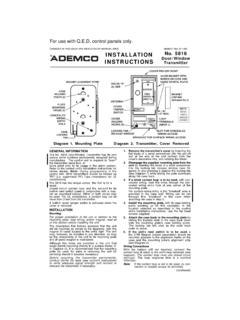
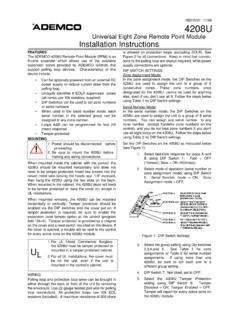
Transcription of INSTALLATION GUIDE - info-techs.com
1 N6752V8 8/98 REMOTE KEYPADS6128, 6137, 6137R, 6138, 6139, & 6139 RINSTALLATION GUIDEKEYPAD FEATURES6128 Fixed-WordKeypad6137/6137 RFixed-WordKeypad61381-Line AlphaKeypad6139/6139R2-Line AlphaKeypadBacklit DisplayNoYes (see note below) Yes (see note below)Yes (see note below)Dedicated Panic KeysNoYesYesYesFlush Mount OptionNoNoYesYesAll the above keypads have backlit keys, are keypad addressable, have a Red ARMED indicator and a Green READY CONTROLSttt tVIA16*/4110XM* / 4110DL*YesYes, 6137 NoNoVIA30P */ VIA30 PSE *YesYes, 6137 YesYes, 6139 VISTA 10SE */VISTA 20SE *YesYes, 6137 YesYes, 61394120XM *YesYes,6137 NoYes, 61394140 XMP */VISTA 40 **YesYes, 6137 NoYes, 6139 VISTA-50 P **/VISTA-50 UL **/VISTA-128B **YesYes, 6137 NoYes, 61395110XM */5120XM *NoYes, 6137 or6137R**NoYes, 6139 or6139R**5140XM **/VISTA-32FB **/VISTA-100 **/VISTA 128FB **NoNoNoYes.
2 6139 or6139R** A 2-Line alpha-numeric display keypad must be used to program these Use non-addressable mode with these controls (set to address 31).QQ Use addressable mode (addresses 00 30).QQQ Keypad color subject to approval of local authority having : Permanent display backlighting is an option on some controls; see the control's INFORMATIONThe 6128, 6137, 6137R, 6138, 6139, and 6139R Remote Keypads arekeypad addressable (no DIP switches), and are intended for use withthe controls listed in the table above. They can be set for the non-addressable operation (address 31) if required by the control withwhich they are : The 6137R and 6139R have red bezels instead of , they are exactly the same as the 6137 and 6139, 6128 and 6137 are fixed-word keypads that provide two-digitnumerics for zone identification, and a set of pre-designated Englishlanguage prompts ( , ALARM, AWAY, STAY, CHECK, etc.)
3 Forindicating the system's status. The 6138 is a one-line alpha keypadthat displays a 2-line message one line at a 6139 is a two-line alpha keypad equipped with a programmable 2-line, 32-character (16 characters per line) English language display forcomplete zone identification (if descriptors are programmed), plussystem status. To display the second line of information, press the [#]key. Press the [#] key again to return to the first line of display automatically returns to the first line of information if nokey is pressed for three : After pressing the [#] key to view the second line or return tothe first line, wait at least three seconds before entering a control panelcommand ( , arm the system).
4 The keys on the keypads are located behind a decorative door, and arecontinuously backlit for convenience. The inside of the decorative doorhas space for a zone ID label (supplied) on which the installer can writedescriptions of each zone for handy user keypads allow panic alarm activation (if enabled in controlprogramming). For the 6128, panic alarms are activated by pressingkey pairs [1] & [Q], [Q] & [#], and [3] & [#]. The 6137/6137R, 6138, and6139/6139R are equipped with dedicated single keys for panicactivation keys A, B, and C (the D key is not used as panic), whichare equivalent to the [1] & [Q], [Q] & [#], and [3] & [#] keys, panic keys (A, B, and C) must be held down for at least2 seconds to activate an set of adhesive-backed labels with some typical panic symbols ( ,fire, police, personal emergency, etc.)
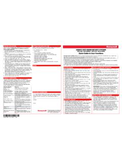
5 Is provided. These labels can beplaced on or next to the keys to identify each key's function for the enduser (as determined by the control panel's capability and programming;see the control's instructions).WIRING AND INSTALLATIONThe keypads can be surface mounted directly to a drywall, or to asingle- or double-gang electrical box. For flush mounting the 6138 and6139/6139R to drywall, use the optional 6139 TRK Flush Mount Kit(6128 & 6137/6137R cannot be flush mounted).1. Remove the case back by pushing down two "snaps." See diagram onthe next Route wiring from the control panel through the opening in the Mount the case back to a wall or electrical Plug the supplied flying lead connector into the keypad PC boardand splice the panel wiring to it, or wire directly to the terminalblock on the PC board (wire colors are marked next to terminals).
6 Wire colors and functions are described in the Re-attach the keypad to its case Remove the clear protective films from the LCD display and *#INSTANTCODECHIMEMAXTESTBYPASSOFFAWAYST AYR emovecase backby pushingdown the 2 snaps along thekeypad stop edgeand pullingthe OF DEDICATED PANIC KEYS. D KEY NOT USEDFOR PANIC THE KEYPAD ADDRESSThe keypad can be set for an address of 0-31 (the keypad will notaccept entries greater than 31), which is stored in EEROM keypad's default address is 31 (non-addressable mode some earlyversions of 6139/6139R default to 11).To change the keypad's address, do the following:1. Enter address mode: Power up (plugin) the keypad. Within 60seconds of power-up, press and hold down the [1] and [3] keys at thesame time for 3 seconds.
7 (If unable to enter address mode, power upand try again.)The current keypad address will be displayed, and the cursor will beunder the "tens" digit. If 10 seconds have passed with no key entry,the keypad automatically exits address mode. You must powerdown, power up and start address mode : The keypad will not enter address mode if the panel to whichit is connected is in programming Set the current address to "00": Press [0] to clear the current "tens"digit. The cursor will move to the "ones" digit position. Press [0] toclear the current "ones" digit. The cursor will move back to the"tens" digit Enter the keypad's address: Enter the proper "tens" digit of thekeypad's address. The cursor will move to the "ones" digit the proper "ones" digit of the keypad's address.
8 Note thataddress "31" sets the keypad to non-addressable Exit address mode:Press [Q] to save the displayed address and exit address THE KEYPAD ADDRESSP ress and hold down the [1] and [3] keys at the same time for about 3seconds. The current address is displayed. No key entry is any key to exit or wait 10 seconds to exit viewing :6128: 4-3/4"H x 5-3/4"W x 1"D (121mm x 146mm x )6137/6137R: 4-3/4"H x 6-1/4"W x 1"D (121mm x 159mm x 26mm)6138/6139/6139R: 4-3/4"H x 6-3/4"W x 1-1/4"D(121mm x 159mm x 32mm)Wiring:Red:+12 VDC(all Keypads) :If present, not :Data to control :Data from control :6128:40mA sounder on, 20mA standby, alarm sounder : 85mA (ARMED LED lit, LCD backlight and sounder on),reduces to 40mA when panel is operating in standbymode (backlight off).
9 6139/6139R: 100mA (ARMED LED lit, LCD backlight and sounderon), reduces to 40mA when panel is operating in standbymode (backlight off).Displays:6138:1 x 16 alpha-numeric supertwist LCD, ,6139R: 2 x 16 alpha-numeric supertwist LCD, , 6137:Fixed-Word LCD (6137 backlit).Sounder: Piezo-electric (fire alarm is loud, pulsing single tone;(all Keypads) burglary alarm is loud, continuous, dualtone).REFER TO INSTALLATION INSTRUCTIONS FOR THE CONTROL PANEL FOR DETAILS ON LIMITATIONS OF THE ENTIRE ALARM LIMITED WARRANTYA larm Device Manufacturing Company, a Division of Pittway Corporation, and its divisions, subsidiaries and affiliates ("Seller"), 165 Eileen Way, Syosset, New York 11791, warrants its productsto be in conformance with its own plans and specifications and to be free from defects in materials and workmanship under normal use and service for 24 months from the date stamp control onthe product or, for products not having an Ademco date stamp, for 12 months from date of original purchase unless the INSTALLATION instructions or catalog sets forth a shorter period, in whichcase the shorter period shall apply.
10 Seller's obligation shall be limited to repairing or replacing, at its option, free of charge for materials or labor, any product which is proved not in compliancewith Seller's specifications or proves defective in materials or workmanship under normal use and service. Seller shall have no obligation under this Limited Warranty or otherwise if the productis altered or improperly repaired or serviced by anyone other than Ademco factory service. For warranty service, return product transportation prepaid, to Ademco Factory Service, 165 EileenWay, Syosset, New York ARE NO WARRANTIES, EXPRESS OR IMPLIED, OF MERCHANTABILITY, OR FITNESS FOR A PARTICULAR PURPOSE OR OTHERWISE, WHICH EXTEND BEYOND THEDESCRIPTION ON THE FACE HEREOF.