Transcription of INSTALLATION GUIDE - Rondo
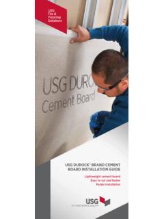
1 INSTALLATION GUIDESTEEL STUDDRYWALL FRAMING SYSTEMS Rondo steel stud & trackDRYWALL FRAMING SYSTEMSINTRODUCTIONR ondo Steel Stud Drywall Framing Systems provide designers with a versatile and durable framing system, manufactured to Australian and New Zealand FOR Non-load and load bearing (by design) partition walls Steel Stud Ceiling Systems Window and Door Jambs Non-Fire Rated and Fire Rated Systems Acoustic Wall Systems (by design) External Wall systems (by design) Light Weight Floor Joists Bulkheads Seismic Wall System (by design)SPECIAL FEATURES Available in custom lengths Majority of Stud and Track is hemmed for safety and increased strength, preventing unwanted rotation Flexible Track available for curved walls Manufactured from BlueScope Steel with a minimum coating of Z275 Profile widths range from 51 to 150mm, and gauges from to Includes unique QUIET STUD profile for better acoustic performance Bell-mouthed service holes to mitigate damage to servicesWHY USE Rondo STEEL STUD & TRACKD esigned to be not only stronger, but safer, our range of Hemmed Stud and Track sections help reduce handling injuries on site.
2 The hemmed return lip increases rigidity, preventing unwanted rotation as well as eliminating sharp Steel Stud Drywall Framing Systems comply with all relevant Building Codes for fire-rated, acoustic, seismic and load-bearing availability of various sizes, complementary components such as nogging tracks, curved tracks and special cleats ensures Rondo Stud and Track Wall Systems are available to suit almost all situations, such as internal drywall partitions up to 10 metres in height, depending on the that this brochure is intended to be used as a GUIDE only; full details should be obtained via the Rondo website. Rondo recommends INSTALLATION by a qualified tradesperson and that you ensure you are referring to the latest version of this GUIDE by comparing it to the one on our website. INSTALLATION of complex or load-bearing wall systems should be undertaken by a qualified details in this brochure may not be suitable for fire-rated or acoustic applications, and Rondo recommends consulting a suitably qualified Rondo DUO COMPONENTSWALL STUDQUIET STUD HEMMED STUDDUPLEX STUD HEMMED WALL TRACKHEMMED DEFLECTION HEAD TRACKNOGGING TRACKSNAP-LOCK NOGGING FLEXIBLE TRACKNOGGING BRACKETFAST-FIX NOGGING 545 STEEL STUD & TRACK COMPONENTSNOTE: DO NOT RIGIDLY FIX CORNICE TO WALLS WHERE FRICTION JOINTS OR DEFLECTION HEADS ARE steel stud & trackINSTALLATION DETAILS1 SYSTEM SELECTION Using Table 1 below, choose the stud appropriate to your wall height and the lining board you desire to use.
3 Then select tracks to match size and gauge of chosen studs. 2 SET OUT AND INSTALLATION Install the floor and ceiling track to suit your wall layout and secure to the structure at no less than 600mm centres internally, and 100mm from ends. For information on the appropriate fixings, consult your Rondo Network INSERT WALL STUDS Insert Wall Studs into Wall Tracks at the appropriate position, ensuring all studs are facing the same way. Wall studs are designed to be friction fitted into the tracks, and are installed using a twisting action. Ensure service holes in studs are aligned. Studs are braced by the application of the lining board, so do not require permanent fixing. 4 INTERSECTIONS Figures 1 & 2 show typical wall intersections whilst Figures 4 & 5 show typical ceiling intersections. For more complex connections, refer to the Rondo website or consult your Rondo Network Partner.
4 5 CONTROL JOINTS Plasterboard manufacturers recommend control joints be installed in continuous walls at not more than 12m. Refer Figure 3. 6 PLASTERBOARD LINING While plasterboard manufacturers should be consulted about linings, it is critical that lining boards be installed to the open side of the stud first to ensure misalignment of joints does not occur in vertical fixing 1: MAXIMUM WALL HEIGHTS6 10mm clearance to stud and lining board 100mm downto first fixingTrack fixing600mm max spacingStandard Top TrackFURRING CHANNELF ixings at each furring channelTOP CROSS RAILC ornice100mm first fixing FIGURE 5: FRICTION FIT APPLICATION FIGURE 4: WALL/CEILING INTERSECTION DETAIL WITH FRICTION FIT FOR CORNICE APPLICATIONS100mm maxtrack fixingUse masonry fixings at 500mm centres along stud height FIGURE 1: INTERSECTION MASONRY FIGURE 2: CORNER SINGLE LAYER APPLICATION FIGURE 3.
5 STUD WALL CONSTRUCTION WITH CONTROL JOINT100mm max100mm max600mm max20mm max gapP35 Control JointStudStudP35 Control JointPLASTERBOARD LININGS SINGLE STUDS @ 600mm WIDTH51mm64mm76mm92mm64mm76mm92mmLINED BOTH SIDES1x10mm27703330370045403930443048301 x13mm32003720413049404220502055001x16mm3 380391043005180435052505710 LINED ONE SIDE1x10mm23202720320036103130358041301x 13mm23202720324036103250382041801x16mm23 202720325036103280387042001000mm max1500mm maxDETAIL ADETAIL BDo not fix through the top track to the studDoor head trimmer from trackBoxed studs or DUPLEX Stud at window & door openingsWINDOW & DOOR FRAMINGF igure 6 details standard fixings suitable for window openings up to 1500mm and standard single leaf door openings. For configurations outside of these limits and external wall framings, consult your local Rondo : Studs adjacent to window and door openings should be boxed and screw-fastened to the bottom wall , use the one-piece DUPLEX Stud fixed in the same manner.
6 Allow sufficient length on each end of the track to facilitate a suitable connection at the head or sill. Fit studs above and below the window openings and above the door openings as per Detail produces three different noggings for steel stud walls. One is installed whilst the framing is being constructed and the other two after the framing is complete. All are available to suit stud centres of 300, 400, 450 & 600mm. The requirement for noggings in your wall can be determined by Table 2. For more complex technical details, view the Rondo Professional Design Manual or speak to a stockist in our Rondo Partner Network. Download a copy of the Manual and locate a Rondo Partner by visiting our board fixing details, please see the plasterboard manufacturer. FIGURE 6: INTERNAL WALL FRAMING DETAIL A: DOOR/WINDOW HEAD DETAIL DETAIL B: VARIOUS DOOR JAMB DETAILS Timber Door Jamb with Stopping Bead to Lining Board Typical detail for timber door frame secured to DUPLEX Stud with optional shadowline detail shownWALL HEIGHT (m)LINING CONDITIONNUMBER OF NOGGINGS0 ONE +4 NOTE: Walls connected to the underside of a concrete slab must be installed with deflection head track and an additional row of Noggings 100mm down if unlined, or lined one side 2.
7 MINIMUM NUMBER OF NOGGINGSSTANDARD NOGGING TRACK This is laid over the top of the floor track and once the studs are placed in the punched slots in the track, it is slid up into place and screwed, both sides, to the studs, usually at the mid-point with #8 wafer or lost head NOGGING The Rondo SNAP-LOCK Nogging is designed for use with Rondo and lightweight studs. SNAP-LOCK clips into the bellmouth service holes in a continuous, overlapping manner after the framing is installed. It is important to ensure the service holes align NOGGING This is also installed after the framing is complete. The primary fixing method is to use the bend out tab as shown in Figure 10, the tab being scored at the bend points, and screw fixed with a #8 wafer or lost head screw. However, for simple full height stud walls lined both sides or one side, the face fix method can be used as shown in noggings are not used continuously but are staggered, one up one down as shown in Figure 12.
8 FIGURE 9: CONTINUOUS INSTALLATION OF SNAP-LOCK NOGGING BETWEEN Rondo STEEL STUDS FIGURE 7: STANDARD NOGGING TRACK DETAILSFix noggingsat each stud FIGURE 8: OVERLAPPING OF SNAP-LOCK NOGGING WHEN CONTINUOUS FIGURE 10: BACK VIEW OF TAB/FACE FIX x 3 SCREWS INSTALLATION METHOD FIGURE 11: FAST-FIX NOGGING INSTALLED INTO Rondo STEEL STUD USING FACE-FIX x 2 SCREWS METHOD FIGURE 12: FAST-FIX NOGGING INSTALLATIONFor more detailed information on Rondo Noggings, refer to the Nogging Manual on our website, or speak to a reseller in our Rondo Partner services MUCH MORE THAN JUST QUALITY PRODUCTSWe go beyond supplying you with quality products. We give you access to a full suite of tools and services to help you get the job done right and with the confidence that we ll support you every step of the SUPPORT We offer expert technical advice from our team of professional Engineers and Technical Representatives who can support you from beginning concepts all the way through to building WARRANTY Our products are 100% code compliant and we guarantee that they ll perform to our exacting specifications with a written warranty to give you added peace of QUALITY Our state-of-the-art manufacturing technology ensures you receive the highest quality product, with most of our roll-formed products manufactured from the strength of BlueScope CONTROL We have a reputation for uncompromising quality and total code compliance.
9 Our certification to internationally recognised, Lloyd s Register Quality Assurance ISO 9001 is evidence of SERVICE We offer a reliable and efficient delivery service, with products delivered in full and on time whether it is on site or to RESOURCES We ve developed market-leading technical resources that are available in print and digitally to help you get the job It s our reputation for high-quality products backed by exceptional customer service that has led to us being behind the best buildings around the world. It s a reputation you can rely PERFORMANCE We can offer you additional Green Points due to our participation in the Environmental Sustainability Charter and our Environmental Management System is accredited to SOCIAL RESPONSIBILITY Through purchasing Rondo products, you are also supporting local communities we give back to. We re focused to help kids with cancer, with our main partner, The Kids Cancer Project.
10 Their goal is to reduce the rate of childhood cancer through funded research , QUIET STUD, DUPLEX STUD, FAST-FIX NOGGING and SNAP-LOCK NOGGING are registered trademarks of Rondo Building Services Pty Ltd. ABN 69 000 289 207. First Printed MAY 2009. Revised JUNE 2020.