Transcription of INSTALLATION INSTRUCTIONS 90+ Two Stage & Two Stage ...
1 440 01 2024 04 Dec. 2010 Specifications are subject to change without INSTRUCTIONS90+ Two Stage & Two Stage , VariableCategory IV, Gas FurnaceC9 MVX, H9 MVX, T9 MVX, C9 MPV, H9 MPV,T9 MPV, C9 MPT, H9 MPT, T9 MPT(Upflow/Downflow/Horizontal)These INSTRUCTIONS must be read and understood completely before attempting Labeling and Signal WordsDANGER, WARNING, CAUTION, and NOTEThe signal words DANGER, WARNING,CAUTION, and NOTE are used to identify levels ofhazard seriousness. The signal word DANGER isonly used on product labels to signify an immediatehazard. The signal words WARNING, CAUTION,and NOTE will be used on product labels andthroughout this manual and other manual that mayapply to the Immediate hazards which will result insevere personal injury or Hazards or unsafe practices whichcould result in severe personal injury or Hazards or unsafe practices whichmay result in minor personal injury or product orproperty Used to highlight suggestions which willresult in enhanced INSTALLATION , reliability, oroperation.
2 !WARNINGS ignal Words in ManualsThe signal word CAUTION is used throughoutthis manual in the following manner:!CAUTIONS ignal Words on Product LabelingSignal words are used in combination withcolors and/or pictures or product signal word WARNING is used throughoutthis manual in the following manner:Safety alert symbolWhen you see this symbol on the unit and ininstructions or manuals, be alert to thepotential for personal OF CONTENTSS tart-up Check Sheets considerations INSTALLATION Requirements & Ventilation Air and Combustion Air Piping Vent Termination Supply and Piping Wiring and Filter and Adjustments Maintenance of Operation & Diagnostics (*9 MPT) Diagram *9 MPT (Two- Stage Heating with PSC Motor) of Operation & Diagnostics (*9 MPV, *9 MVX) Diagram *9 MPV, *9 MVX (Variable Speed Blower Motor) Wiring Guide of the AHRI Certified TM Mark indicates amanufacturer s participation in the verification of certification for individualproducts, go to.
3 International Comfort Products, LLCL ewisburg, TN 37091 !WARNINGPERSONAL INJURY, AND/OR PROPERTYDAMAGE HAZARDF ailure to carefully read and follow this warning couldresult in equipment malfunction, property damage,personal injury and/or or repairs made by unqualified persons couldresult in equipment malfunction, property damage,personal injury and/or information contained in this manual is intended foruse by a qualified service technician familiar with safetyprocedures and equipped with proper tools and must conform with local building codes andwith the Natural Fuel Gas Code (NFCG) NFPA 54 , and National standards of CanadaCAN/CSA and .2 Natural Gas and PropaneInstallation : Affix these INSTRUCTIONS on or adjacent to : Retain these INSTRUCTIONS for of the text and tables are reprinted from NFPA 54 /ANSI 2009 , with permission of National Fire Protection Association, Quincy, MA 02269 and American Gas Association, Washington, DC20001.
4 This reprinted material is not the complete and official position of the NFPA or ANSI, on the referenced subject, which is represented only by the standard in its 01 2024 04 Specifications are subject to change without Notice for Massachusetts InstallationsImportantThe Commonwealth of Massachusetts requires compliance with regulation 248 CMR as : Modifications to NFPA 54, Chapter 102) Revise by adding the following additional requirements:(a) For all side wall horizontally vented gas fueled equipment installed in every dwelling, building or structure used in whole or in part for residentialpurposes, including those owned or operated by the Commonwealth and where the side wall exhaust vent termination is less than seven (7) feetabove finished grade in the area of the venting, including but not limited to decks and porches, the following requirements shall be OF CARBON MONOXIDE DETECTORS.
5 At the time of INSTALLATION of the side wall horizontal vented gas fueled equipment, theinstalling plumber or gasfitter shall observe that a hard wired carbon monoxide detector with an alarm and battery back up is installed on thefloor level where the gas equipment is to be installed. in addition, the installing plumber or gasfitter shall observe that a battery operated or hardwired carbon monoxide detector with an alarm is installed on each additional level of the dwelling, building or structure served by the side wallhorizontal vented gas fueled equipment. It shall be the responsibility of the property owner to secure the services of qualified licenseprofessionals for the INSTALLATION of hard wired carbon monoxide In the event that the side wall horizontally vented gas fueled equipment is installed in a crawl space or an attic, the hard wired carbonmonoxide detector with alarm and battery back up may be installed on the next adjacent floor In the event that the requirements of this subdivision can not be met at the time of completion of INSTALLATION , the owner shall have a periodof thirty (30) days to comply with the above requirement; provided, however, that during said thirty (30) day period, a battery operatedcarbon monoxide detector with an alarm shall be CARBON MONOXIDE DETECTORS.
6 Each carbon monoxide detector as required in accordance with the above provisions shallcomply with NFPA 720 and be ANSI/UL 2034 listed and IAS A metal or plastic identification plate shall be permanently mounted to the exterior of the building at a minimum height of eight (8)feet above grade directly in line with the exhaust vent terminal for the horizontally vented gas fueled heating appliance or equipment. The signshall read, in print size no less than one half (1/2) inch in size, GAS VENT DIRECTLY BELOW. KEEP CLEAR OF ALL OBSTRUCTIONS . The state of local gas inspector of the side wall horizontally vented gas fueled equipment shall not approve the installationunless, upon inspection, the inspector observes carbon monoxide detectors and signage installed in accordance with the provisions of 248 CMR (2)(a) 1 through 4.
7 (b) EXEMPTIONS: The following equipment is exempt from 248 CMR (2)(a) 1 through 4 equipment listed in Chapter 10 entitled Equipment Not Required To Be Vented in the most current edition of NFPA 54 as adopted by theBoard; Approved side wall horizontally vented gas fueled equipment installed in a room or structure separate from the dwelling, building orstructure used in whole or in part for residential purposes.(c) MANUFACTURER REQUIREMENTS GAS EQUIPMENT VENTING SYSTEM PROVIDED. When the manufacturer of Product Approved side wallhorizontally vented gas equipment provides a venting system design or venting system components with the equipment, the INSTRUCTIONS provided bythe manufacturer for INSTALLATION of the equipment and the venting system shall INSTRUCTIONS for the INSTALLATION of the venting system design or the venting system components; complete parts list for the venting system design or venting system.
8 (d) MANUFACTURER REQUIREMENTS GAS EQUIPMENT VENTING SYSTEM NOT PROVIDED. When the manufacturer of a Product Approvedside wall horizontally vented gas fueled equipment does not provide the parts for venting the flue gases, but identifies special venting systems , thefollowing requirements shall be satisfied by the referenced special venting system INSTRUCTIONS shall be included with the appliance or equipment INSTALLATION INSTRUCTIONS ; special venting systems shall be Product Approved by the Board, and the INSTRUCTIONS for that system shall include a parts list and detailedinstallation INSTRUCTIONS .(e) A copy of all INSTALLATION INSTRUCTIONS for all Product Approved side wall horizontally vented gas fueled equipment, all venting INSTRUCTIONS , all parts listsfor venting INSTRUCTIONS , and/or all venting design INSTRUCTIONS shall remain with the appliance or equipment at the completion of the questions regarding these requirements, please contact the Commonwealth of Massachusetts Board of State Examiners of Plumbers and GasFitters, 239 Causeway Street, Boston, MA 02114.
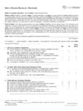
9 617 727 99523 Specifications are subject to change without 01 2024 04 START UP CHECK SHEETFor PSC Models *9 MPT(This sheet is optional. Keep for future reference.)Date of Start Up:Dealer Name:Address:City, State(Province), Zip or Postal Code:Phone:Owner Name:Address:City, State(Province), Zip or Postal Code:Model Number:Serial Number:Setup ChecksCheck the box when task is Electrical Connections Tight? Have hoses been relocated for furnace U/D/Happlication? Condensate Drain Connected? Condensate Drain Trapped? Manual Gas Shut off Upstream of Furnace/Drip LegGas Valve turned ON? Type of Gas: Natural: propane : Filter Type and Size:Shade in Heating Fan Time OFF Setting and ThermostatType setting:Calculated Input (BTU) Rate: (See Checks andAdjustments Section).
10 Heating CheckMeasured Line Pressure During High Heat: Measured Manifold Pressure: High Heat Low Heat Temperature of Supply Air: High Heat Low Heat Temperature of Return Air: Temperature Rise (Supply Return): High Heat Low Heat In Rise Range (see furnace rating plate)? Static Pressure (Ducts) High Heat: Supply Return The Blower Speed Tap used for: High Heat Low Heat Optional Check: CO? CO2? Cooling CheckTemperature of Supply Air: Temperature of Return Air: Temperature Difference: Static Pressure (Ducts) Cooling: Supply Return The Blower Speed Tap used for: Cooling Dealer Comments:4440 01 2024 04 Specifications are subject to change without UP CHECK SHEETFor Variable Speed Models *9 MPV, *9 MVX(This sheet is optional.)