Transcription of Installation Instructions - Aquatic Bath
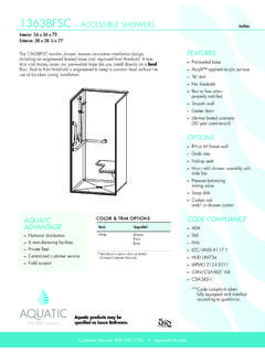
1 Installation InstructionsAcrylic Shower ModulesW89"(2260)D6" cutoutforshowersSoffit header installed after unit is in place 6 x12 cutout (for tub-showers)Left hand shownFig. 1 FramingA. PRE- Installation PLANNING1. Unit must be placed within bathroom area before com ple tion of door framing or, if preferred, studs may be omitted or knocked-out to permit unit Make sure framed-in alcove is of proper size, square and plumb; check floor for If fire-rated alcove is required, approved finish material must be in place prior to unit in stal la tion to meet fire safety requirements of local building code and/or FHA/HUD Minimum Property Stan dards. NOTE: finished alcove must have interior dimensions shown on rough-in diagram to permit Installation of Casting plaster or other foundation materials are recommended. Shim ming may be needed to level unit and for additional If a shower door is to be installed, measure en clo sure open ing before ordering, or order a Aquatic Door for a quality custom If dome light will be installed, cut out required area within molded 12 (305) sq.
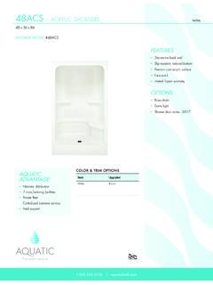
2 Flat area in center of dome. Use fine-tooth or abrasive-grit blade. Cut from inside. Light fixture must have UL label, and be water- and CRITICAL PRE- Installation ROUGH-IN REQUIREMENTSMake sure these provisions have been made before attempting to install unit:1. 6 (150) diameter floor opening for 2 (50) IPS and drain con nec tion [Fig. 1] for shower 6 x 12 (150 x 305) diameter floor opening for drain and overflow plumbing [ ] for tub-shower unit. Be sure hole location matches type of tub-shower: left or right hand Front corner posts are double 2 x 4 (50 x 100) studs for flush mount Shower Module60 Shower ModuleTub-Shower Module W46 (1170)58 (1475) 58 (1495) D36 (915)36 (915)34 (865) HEIGHT, WIDTH DIMENSIONAL TOLERANCE +0, 3 8 ( 5mm)GENERAL DIMENSION TOLERANCE: +3 8 (10mm) , 3 8 (5mm)60 with SeatTub-shower48 with SeatProduct TypeOverall Dimensions: Inches (mm)48 Shower Module48 W X 36 D X 90 H60 Shower Module60 W X 36 D X 90 HTub-Shower Module60 W X 34 D X 90 HInstallation InstructionsAcrylic Shower ModulesC.
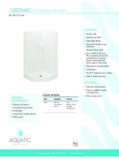
3 Installation PROCEDURE1. To avoid obstruction, make sure that supply lines and valve plumbing are not strapped to studs and do not project into On outside of plumbing endwall of unit, mark locations of shower arm, valve/s and tub spout in ac cor dance with di men sions shown in Fig. 2 and Fig. 3. Double-check location of marks. Drill 1 4 (5) pilot From inside of unit [glossy side], using proper size hole saw with fine-tooth or abrasive grit cutting edge, cut openings for shower arm, valve/s and tub spout. Fasten shower drain fitting at this If using casting plaster, mix 3 gallon bucket. Place 3 or 4 mounds starting near drain approximately twice as high as the cavity under the Place unit into alcove use care not to crack or break lower corners when pushing or walking unit into alcove. NOTE: If shower drain fitting does not nest with drain pipe, tilt unit forward while adjusting drain pipe.
4 Be sure unit s weight does not rest on drain Level unit for proper drainage. Use a 3 (915) long level on top of dam and on front face. Shim where necessary to assure level unit, or depress grout mounds until Install soffit header above unit as shown in Fig. Using holes provided, screw [do not nail] unit to framing. For wood framework, use #8 x 11 2 (40) flathead wood screws. For metal framework, use #8 x 11 2 (40) sheet metal screws. Start at holes at lower left and right, pro ceed ing upward alternately on each side and across the top. Drive screws snugly but do not overtighten. CAUTION: Do not nail into face of mounting flange. Do not strike flange with any tool. Striking unit may cause irreparable Make final connections to supply lines and waste pipe in accordance with plumbing code re quire ments. Strap water lines and valve/s to Finish front of the unit with drywall, as shown [Fig.]
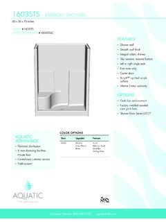
5 4].D. CLEAN-UP1. DO NOT REMOVE WARRANTY LABEL! Leave on the unit for owner or occupant. [Code Requirement]2. Use sponge with warm water and a liquid non-abrasive detergent. DO NOT USE scouring pads, steel wool, metal scrapers, sand paper or anything else that might scratch, mar, or dull the finish. Plaster, latex paint, or other foreign materials may be removed with water, liquid detergent, and plastic scraper. CAUTION: DO NOT USE heat or solvent based cleaning Dull areas and light scratches may be removed by buffing with a light colored automotive rubbing compound and soft cloth. Entire unit can be waxed with light colored automotive wax. DO NOT WAX BOTTOM OF PREVENT STAINING. Remove all debris before leak testing for plumbing inspection. Drain and wipe clean immediately after testing and inspection .MODULESHOWERSTRIPFURRINGFRAMING2" X 4"DRYWALLFig. 4 Not to scaleVALVE AND SHOWER ARM LOCATIONSHOWERTUB SHOWER82"24"36"17"SHOWERARMVALVESTUB SPOUT82"43"19"SHOWERARMVALVESGEN4023