Transcription of INSTALLATION INSTRUCTIONS - Brandmotion
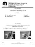
1 INSTALLATION INSTRUCTIONS 1009-6503 Page 1 of 10 Rear Vision System Aftermarket and Factory , and MyGig Touch Screen Display (Factory Display requires Chrysler/ dodge dealer to activate) 2009 Current* dodge Ram (Kit part number 1009-6503) *NOTE: 2013 and newer Ram vehicles require raising Reverse signal voltage using a Single Pull Dual Throw Relay when used with aftermarket mirrors and displays. (Please refer to detailed INSTALLATION steps on Page 7 of these INSTRUCTIONS .) Please read thoroughly before starting INSTALLATION and check that kit contents are complete. Items Included in the Kit: Chassis Harness with RCA** Tailgate Handle with Camera , Factory Touch Screen Jumper Harness (2013 to present Ram option only)** MyGig Factory display 22-pin camera input harness (2009 to 2012)* 1 bag containing: Plug for Non-Locking Tailgates (Optional) Red wire with terminal for older vehicles (optional) Black wire with terminal for older vehicles (optional) 1 bag containing: These INSTRUCTIONS Template **In some cases a RCA extension may be required to connect to your aftermarket display.
2 Kit# 9002-6111 may be purchased from Tools Required: Socket Wrench with 7mm & 8mm Sockets T20 and T30 Torx Bits Phillips and Flat Blade Screwdrivers Power Drill 1/8 Drill Bit 1 Hole Cutter Pushpin Removal Tool Round File or Deburring Tool Center Punch Utility Knife or Side Cutters Masking Tape Corrosion Inhibitor (recommended) Soldering Iron & Solder (recommended) Wire Ties (recommended) We strive to provide accurate and up-to-date INSTALLATION INSTRUCTIONS . For the latest full color INSTRUCTIONS , please visit Install Tailgate Handle Camera 1. Set up a work area on which to set the tailgate after removal. This area should be well protected to avoid damage to tailgate. 2. For 2013 and newer Ram vehicles ONLY, (older vehicles, please proceed to Step 3) use your fingers to remove the black plastic filler panel at rear of pickup bed adjacent to the license plate.
3 Press on the end tab and lifting outward. Next, slide the red tab from the locked position and unplug the tailgate power lock harness connector. INSTALLATION INSTRUCTIONS 1009-6503 Page 2 of 10 3. Unhook both tailgate support straps by inserting a Flat Blade Screwdriver between the locking tab and strap mount. Lift the locking tab away from the strap mount with the screwdriver while sliding the tailgate strap upwards. The tailgate strap hanger can now be removed from the mount. 4. Open tailgate about ten degrees and lift right side of the tailgate off the pin. Next, slide tailgate to the right to remove taking care not to damage the paint. NOTE: Tailgate removal and INSTALLATION requires two people. 5. Remove the handle access panel inside the tailgate using a T30 Torx driver.
4 (NOTE: If vehicle is equipped with a bed liner, the tailgate portion of the liner must be removed prior to this step.) 6. Remove nuts attaching handle to tailgate using an 8mm Socket, then remove handle from tailgate. (NOTE: Non-power locking tailgate mechanism shown.) 7. If equipped, remove the lock cylinder from existing handle. 8. If equipped, remount the lock cylinder in the supplied Tailgate Camera Handle using a 8mm Socket and existing hardware. Follow Steps 9 through 21 for 2013 and newer Ram vehicles ONLY: 9. Use a Utility Knife or Side Cutters to remove the Rubber Grommet closest to the camera end from the Camera Harness. Wrap the Camera Harness with Electrical Tape where you removed the grommet. INSTALLATION INSTRUCTIONS 1009-6503 Page 3 of 10 10.
5 Route the gray Camera Harness connector and wiring through tailgate and install supplied handle using a 8mm Socket with the existing hardware. 11. Reinstall handle bolts. 12. Route the supplied Camera Harness through the pass-through hole in the inner brace of the tailgate. 13. Route Camera Harness through the rectangular hole in the bottom of the tailgate. 14. Use Masking Tape to affix supplied Template B above the oval spare tire access slot (located just right of center on the pickup bed rear edge) and mark the hole center using a Center Punch. 15. Check the area behind the hole you marked for wiring. If any wiring is present, secure it away from the area to be drilled. 16. Use a 1/8 drill bit to make a pilot hole at the center punch mark. Then use a 1 Hole Saw to make the Camera Harness pass through hole.
6 17. RECOMMENDED: Use a Cotton Swab or small brush to apply Corrosion Inhibitor to exposed edges. 18. Taking care not to damage the Camera Harness, reinstall tailgate by lifting it into place, rotating it down about ten degrees, and sliding it to the left. 19. Reinstall both tailgate straps by placing the large opening of the tailgate strap hangers over the tailgate strap mounts and pulling down. Proceed to Step 33. 20. Seat the Camera Harness grommet in the pass through hole you drilled in the end of the pickup bed using your fingers. 21. Plug in the tailgate power lock harness connector (removed in Step 2) and slide the red tab to the locked position. Reinstall the black plastic filler panel at rear of pickup bed adjacent to the license plate. INSTALLATION INSTRUCTIONS 1009-6503 Page 4 of 10 Follow Steps 22 through 32 for 2009 through 2012 Ram vehicles ONLY 22.
7 Use a Utility Knife or Side Cutters to remove the Rubber grommet closest to the gray connector end from the Camera Harness. Wrap the Camera Harness with Electrical Tape where you removed the grommet. 23. Use Masking Tape to affix supplied Template A to tailgate. An existing small rectangular hole in the center of the lower tailgate edge will match up with the left side of Template A. Use a Center Punch to mark the tailgate at the X on Template A and remove Template A. 24. Use a 1/8 drill bit to make a pilot hole at the center punch mark. Then use a 1 Hole Cutter to cut a pass through in the tailgate. 25. Clean rough edges of the hole using a Deburring Tool or Round File. RECOMMENDED: Apply Corrosion Inhibitor to the metal edges. 26. Route the gray Camera Harness connector and wiring through tailgate and install supplied handle using an 8mm Socket with the existing hardware.
8 27. Reinstall handle bolts. 28. Route the supplied Camera Harness through the pass-through hole in the inner brace of the tailgate. 29. Seat Camera Harness grommet in the pass through hole you drilled in the tailgate using your fingers 30. Taking care not to damage the Camera Harness, reinstall tailgate by lifting it into place, rotating it down about ten degrees, and sliding it to the left. INSTALLATION INSTRUCTIONS 1009-6503 Page 5 of 10 31. Reinstall both tailgate straps by placing the large opening of the tailgate strap hangers over the tailgate strap mounts and pulling down. 32. Feed the gray end of the Camera Harness through the rectangular opening at the rear of the truck bed. Install Chassis Harness 33. Remove front driver s side kick panel/sill plate by lifting it at the rear and working your way forward with your hands.
9 34. Remove rear driver s-side sill plate by lifting it at front and working your way back with your hands. 35. Lift driver s side rear seat to expose the under seat storage compartment. Pull three pushpins out of the driver s side rear seat storage compartment using a Pushpin Removal Tool. 36. Pull back carpeting and remove the body floor plug. 37. Insert the large gray connector end of the supplied Chassis Harness through the body floor plug hole. INSTALLATION INSTRUCTIONS 1009-6503 Page 6 of 10 38. Seat grommet affixed to the supplied Chassis Harness in the body floor plug hole by firmly pressing it with your fingers. 39. Route the Chassis Harness RCA connector through the seat riser reinforcement hole. 40. Reinstall carpet and reinstall the three pushpins removed earlier.
10 41. Route Chassis Harness around B-pillar trim by lifting up on the trim and feeding harness through to front. 42. Continue to route Chassis Harness along the driver s side front door opening sill area. NOTE: This will be a tight fit, as the supplied Chassis Harness will follow the existing wiring harness. 43. Reinstall rear sill plate by pressing it back into place with your hands. 44. Remove driver s side kick panel insulation pad retainers using a Pushpin Removal Tool. Route the supplied Chassis Harness behind the insulation (between insulation and metal frame) then reinstall the insulation). 45. Reinstall front kick panel/sill plate by pressing it back into place with your hands. 46. If needed, install aftermarket display/ Navigation display per manufacturer s INSTRUCTIONS .