Transcription of Installation Instructions - Carrier
1 Specifications subject to change without notice. Fig. 1 size 18 KFig. 2 Sizes 24K and 30 KFig. 3 Sizes 36K and 48 KNOTES: Read the entire instruction manual before starting the are for illustration purposes only. Actual models may differ OF CONTENTSSAFETY LIST ..3 SYSTEM .. UNIT WIRING/PIPING VACUUM AND UNIT DIAGNOSTIC Instructions38 MGRM ulti-zone Outdoor Unit Ductless SystemSizes 18, 24, 30, 36 and 482 Specifications subject to change without notice.
2 IM-38 MGR-05 SAFETY CONSIDERATIONSI nstalling, starting up, and servicing air-conditioning equipment can be hazardous due to system pressures, electrical components, and equipment location (roofs, elevated structures, etc.). Only trained, qualified installers and service mechanics should install, start-up, and service this equipment. Untrained personnel can perform basic maintenance functions such as coil cleaning. All other operations should be performed by trained service personnel. When working on the equipment, observe precautions in the literature and on tags, stickers, and labels attached to the equipment.
3 Follow all safety codes. Wear safety glasses and work gloves. Keep a quenching cloth and fire extinguisher nearby when brazing. Use care in handling, rigging, and setting bulky these Instructions thoroughly and follow all warnings or cautions included in literature and attached to the unit. Consult local building codes and current editions of the National Electrical Code (NEC) NFPA 70. In Canada, refer to current editions of the Canadian electrical code CSA Recognize safety information. This is the safety-alert symbol . When you see this symbol on the unit and in Instructions or manuals, be alert to the potential for personal injury.
4 Understand these signal words: DANGER, WARNING, and CAUTION. These words are used with the safety-alert symbol. DANGER identifies the most serious hazards which will result in severe personal injury or death. WARNING signifies hazards which could result in personal injury or death. CAUTION is used to identify unsafe practices which may result in minor personal injury or product and property damage. NOTE is used to highlight suggestions which will result in enhanced Installation , reliability, or Instructions cover the Installation , start-up and servicing of the multi-zone outdoor unit connected to up to five indoor fan coil units.
5 For approved combinations, refer to the product data SHOCK HAZARDF ailure to follow this warning could result in personal injury or installing, modifying, or servicing system, main electrical disconnect switch must be in the OFF position. There may be more than 1 disconnect switch. Lock out and tag switch with a suitable warning HAZARDF ailure to follow this warning could result in death, serious personal injury, and/or property use air or gases containing oxygen for leak testing or operating refrigerant compressors. Pressurized mixtures of air or gases containing oxygen can lead to an DAMAGE HAZARDF ailure to follow this caution may result in equipment damage or improper not bury more than 36 in.
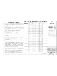
6 (914 mm) of refrigerant pipe in the ground. If any section of pipe is buried, there must be a 6 in. (152 mm) vertical rise to the valve connections on the outdoor units. If more than the recommended length is buried, refrigerant may migrate to the cooler buried section during extended periods of system shutdown. This causes refrigerant slugging and could possibly damage the compressor at Specifications subject to change without notice. 3 PARTS LISTT able 1 Parts List Fig.
7 4 Parts ListNOTES:- If the outdoor unit is higher than the indoor unit, prevent rain from flowing into the indoor unit along the connection pipe by makinga downward arc in the connection pipe before it enters the wall to the indoor unit. This ensures that rain drips from the connectionpipe before it enters the Piping and the interconnecting wiring are field The illustration above (Fig. 4) is only a sketch. Different models may be differ units listed in Table 2 are covered in this 2 Indoor Units Part NameQty1 Outdoor Unit1-Literature package including Installation Instructions and warranty1-Grommet to secure the outdoor unit (helps with vibration prevention during unit operation)4-Drain joint1-Drain hose1-Conversion Joints (see Table 4)-System TonskBTUhV-Ph-HzOutdoor 2 XWGRRU 4 Specifications subject to change without notice.
8 IM-38 MGR-05 SYSTEM REQUIREMENTSA llow sufficient space for airflow and unit service. See Fig. 5 on page 6 for the minimum required distances between the unit and walls or REQUIREMENTSIMPORTANT: Both refrigerant lines must be insulated minimum refrigerant line length between the indoor and outdoor units is 10 ft. (3 m). The following lengths are allowed. Table 3 lists the pipe sizes for the outdoor unit. For the indoor unit pipe sizes refer to the indoor unit Installation 3 Piping and Refrigerant NOTE: For piping runs greater than the Maximum Piping Length with no additional refrigerant charge per System , see Additional Refrigerant Charge (see Table 5).
9 Refrigerant Piping:Line sets to be sized based on the connection size of the indoor unit. Each pipe should be insulated Joints:The outdoor unit includes a package of conversion joints to facilitate Installation of the various fan coil sizes. These joints are to be connected to the outdoor unit as needed to match the line set 4 Conversion Joints Table 5 Additional Refrigerant ChargeAdditional Refrigerant CalculationSum Total Liquid Pipe ft. (m) - Additional Charge Required After ft. (m.) x Additional Charge (g/m) (15)NOTES:If the calculation results in a negative number no additional refrigerant is required.
10 Electronic expansion valves in the outdoor unit are used as metering Size18K24K30K36K48 KPipingMin. Piping Length per each indoor unitft (m)10 (3)10 (3)10 (3)10 (3)10 (3)Standard Piping Length per each indoor unitft (m)25 ( )25 ( )25 ( )25 ( )25 ( )Max. outdoor-indoor height difference (OU higher than IU)ft (m)49 (15)49 (15)49 (15)65 (20)65 (20)Max. outdoor-indoor height difference (IU higher than OU)ft (m)49 (15)49 (15)49 (15)65 (20)65 (20)Max. height different between indoor unitsft (m)32 (10)32 (10)32 (10)32 (10)32 (10)Max. Length per each indoor unitft (m)82 (25)98 (30)115 (35)115 (35)115 (35)Max.