Transcription of Installation Instructions - Carrier
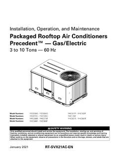
1 WeatherMaker . 48TC 07-16. Single Package Rooftop with Gas Heat/Electric Cooling Installation Instructions 48TC*D/E units for Installation in the United States contain use of Carrier 's Staged Air Volume (SAV ) 2-speed indoor fan control system. This complies with the Department of Energy (DOE) efficiency standard of 2018. 48TC*D/E units for Installation outside the United States may or may not contain Carrier 's Staged Air Volume (SAV) 2-speed indoor fan control system as they are not required to comply with the Department of Energy (DOE) 2018 mandatory efficiency standard. 48TC*M units for Installation inside or outside the United States do not contain use of Carrier 's Staged Air Volume (SAV) 2-speed indoor fan motor control system as they comply with the Department of Energy (DOE) 2018 mandatory efficiency standard without their use. For specific details on operation of the Carrier SAV 2-speed indoor fan system refer to the Variable Frequency Drive (VFD) Factory-Installed Option 2-Speed Motor Control Installation , Setup, and Troubleshooting manual.
2 CONTENTS Step 11 Install External Condensate Trap and Line ..30. Page Step 12 Make Electrical Connections .. 30. SAFETY CONSIDERATIONS .. 2 FIELD POWER SUPPLY (SIZES 07-14). GENERAL .. 3 FIELD POWER SUPPLY (SIZE 16). Rated Indoor Airflow (cfm) .. 3 ALL UNITS. Pre- Installation .. 3 UNITS WITH FACTORY-INSTALLED NON-FUSED. Installation .. 16 DISCONNECT. UNITS WITHOUT FACTORY-INSTALLED NON- Step 1 Plan for Unit Location .. 16 FUSED DISCONNECT. ROOF MOUNT ALL UNITS. Step 2 Plan for Sequence of Unit Installation .. 17 CONVENIENCE OUTLETS. CURB-MOUNTED Installation ALL UNITS. PAD-MOUNTED Installation FACTORY-OPTION THRU-BASE CONNECTIONS. FRAME-MOUNTED Installation (ELECTRICAL CONNECTIONS) (SIZE 07-14). Step 3 Inspect Unit .. 17 FACTORY-OPTION THRU-BASE CONNECTIONS. (ELECTRICAL CONNECTIONS) (SIZE 16). Step 4 Provide Unit Support .. 17 HUMIDI-MIZER CONTROL CONNECTIONS.
3 ROOF CURB MOUNT EconoMi$er X (Factory-Installed Option) ..41. FOR SIZES 07-14 ONLY. SLAB MOUNT (HORIZONTAL UNITS ONLY) PRODUCT DESCRIPTION. ALTERNATE UNIT SUPPORT (IN LIEU OF CURB OR SYSTEM COMPONENTS. SLAB MOUNT) SPECIFICATIONS. INPUTS. Step 5 Field Fabricate Ductwork .. 21 OUTPUTS. Step 6 Rig and Place Unit .. 21 ENVIRONMENTAL. POSITIONING ON CURB ECONOMIZER MODULE WIRING DETAILS. Step 7 Convert to Horizontal and Connect S-BUS SENSOR WIRING. Ductwork (When Required) .. 23 CO2 SENSOR WIRING. SIZES 07-14 INTERFACE OVERVIEW. SIZE 16 USER INTERFACE. ALL UNITS KEYPAD. MENU STRUCTURE. Step 8 Install Outside Air Hood .. 24 SETUP AND CONFIGURATION. ECONOMIZER AND TWO-POSITION DAMPER HOOD TIME-OUT AND SCREENSAVER. PACKAGE REMOVAL (FACTORY OPTION SIZES 07- ENTHALPY SETTINGS. 14) TWO-SPEED FAN OPERATION. TWO-POSITION DAMPER HOOD REMOVAL CHECKOUT. (FACTORY OPTION SIZE 16) TROUBLESHOOTING.
4 ECONOMIZER AND TWO-POSITION DAMPER HOOD PremierLink Control ..54. SETUP (SIZE 16). RTU Open Control System ..54. Step 9 Install Flue Hood .. 26. SMOKE DETECTORS. Step 10 Install Gas Piping .. 26 COMPLETING Installation OF RETURN-AIR. FACTORY-OPTION THRU-BASE CONNECTIONS SMOKE SENSOR. (GAS CONNECTIONS) (SIZES 07-14) ADDITIONAL APPLICATION DATA. FACTORY-OPTION THRU-BASE GAS CONNECTIONS Step 13 Adjust Factory-Installed Options .. 55. (SIZE 16). ALL UNITS SMOKE DETECTORS. Manufacturer reserves the right to discontinue, or change at any time, specifications or designs without notice and without incurring obligations. Catalog No. 04-53480257-01 Printed in Form 48TC-7-16-02SI Rev. A Pg 1 6-21 Replaces: 48TC-7-16-01SI. ECONOMI$ER IV OCCUPANCY SWITCH. Step 14 Install Accessories .. 55 WARNING. Step 15 Check Belt Tension .. 55. BELT FORCE DEFLECTION METHOD UNIT OPERATION AND SAFETY HAZARD.
5 BELT TENSION METHOD Failure to follow this warning could cause personal injury, Pre-Start and Start-Up .. 56 death and/or equipment damage. Troubleshooting the Ultra Tech Compressor .. 56 R-410A refrigerant systems operate at higher pressures than MODULATION CONTROL INPUT SPECIFICATIONS standard R-22 systems. Do not use R-22 service equipment or START-UP CHECKLIST .. CL-1 components on R-410A refrigerant equipment. SAFETY CONSIDERATIONS. WARNING. Installation and servicing of air-conditioning equipment can be hazardous due to system pressure and electrical components. Only PERSONAL INJURY AND ENVIRONMENTAL. trained and qualified service personnel should install, repair, or HAZARD. service air-conditioning equipment. Failure to follow this warning could cause personal injury or Untrained personnel can perform basic maintenance functions of death. cleaning coils and filters and replacing filters.
6 All other operations Relieve pressure and recover all refrigerant before system should be performed by trained service personnel. When working repair or final unit disposal. on air-conditioning equipment, observe precautions in the literature, tags and labels attached to the unit, and other safety Wear safety glasses and gloves when handling refrigerants. precautions that may apply. Keep torches and other ignition sources away from refrigerants and oils. Follow all safety codes, including ANSI (American National Standards Institute) Wear safety glasses and work gloves. Use quenching cloth for unbrazing operations . Have fire extinguisher available for all brazing operations . WARNING. It is important to recognize safety information. This is the safety- CARBON-MONOXIDE POISONING HAZARD. alert symbol . When you see this symbol on the unit and in Instructions or manuals, be alert to the potential for personal Failure to follow Instructions could result in severe personal injury.
7 Injury or death due to carbon-monoxide poisoning, if combustion products infiltrate into the building. Understand the signal words DANGER, WARNING, CAUTION, and NOTE. These words are used with the safety-alert symbol. Check that all openings in the outside wall around the vent DANGER identifies the most serious hazards which will result in (and air intake) pipe(s) are sealed to prevent infiltration of severe personal injury or death. WARNING signifies hazards combustion products into the building. which could result in personal injury or death. CAUTION is used Check that furnace vent (and air intake) terminal(s) are not to identify unsafe practices, which may result in minor personal obstructed in any way during all seasons. injury or product and property damage. NOTE is used to highlight suggestions which will result in enhanced Installation , reliability, or operation.
8 AVERTISSEMENT. RISQUE D'INTOXICATION AU MONOXYDE DE. WARNING CARBONE. Si ces directives ne sont pas suivies, cela peut entra ner des FIRE, EXPLOSION HAZARD blessures graves ou une intoxication au monoxyde de carbone Failure to follow this warning could result in death, serious pouvant causer la mort, si des produits de combustion personal injury and/or property damage. s'infiltrent dans le b timent. Disconnect gas piping from unit when pressure testing at V rifier que toutes les ouvertures pratiqu es dans le mur pressure greater than psig (3450 Pa). Pressures greater than ext rieur autour du ou des tuyaux d' vent (et de la prise d'air). psig will cause gas valve damage resulting in hazardous sont scell es de mani re emp cher l'infiltration de produits condition. If gas valve is subjected to pressure greater than de combustion dans le b timent. psig, it must be replaced before use.
9 When pressure testing Veiller ce que la ou les sorties de l' vent de l'appareil de field-supplied gas piping at pressures of psig or less, a unit chauffage (et la prise d'air) ne soient, en aucune fa on, connected to such piping must be isolated by closing the obstru es, quelle que soit la saison. manual gas valve(s). DANGER. ELECTRICAL SHOCK HAZARD. Failure to follow this warning will result in personal injury or death. Before performing service or maintenance operations on unit, turn off main power switch to unit and install lock(s) and lock- out tag(s). Ensure electrical service to rooftop unit agrees with voltage and amperage listed on the unit rating plate. Unit may have more than one power switch. 2. WARNING AVERTISSEMENT. FIRE HAZARD RISQUE D'INCENDIE OU D'EXPLOSION. Failure to follow this warning could result in severe personal Si les consignes de s curit ne sont pas suivies la lettre, cela injury and/or property damage.
10 Peut entra ner la mort, de graves blessures ou des dommages Inlet pressure tap set screw must be tightened and 1/8-in. NPT mat riels. Ne jamais v rifier la pr sence de fuites de gaz au pipe plug must be installed to prevent gas leaks. moyen d'une flamme nue. V rifier tous les raccords en util- isant une solution savonneuse commerciale con ue sp ciale- ment pour la d tection de fuites. Un incendie ou une explo- sion risque de se produire, ce qui peut entra ner la mort, des blessures ou des dommages mat riels. GAS VALVE. GENERAL. These Installation Instructions cover the 48TC units with gas heat and electric cooling. Units are pre-wired and pre-charged with INLET PRESSURE environmentally balanced Puron (R-410A) refrigerant at the TAP SET SCREW factory. See Fig. 1 for model number nomenclature. See Fig. 2 and 3 (size 07), Fig. 7 (size 08-12), Fig. 8 (size 14), and Fig.