Transcription of Installation Operation Maintenance
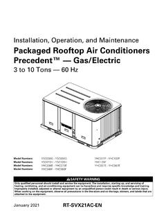
1 InstallationOperationMaintenancePackaged Gas/ElectricYC-IOM-1318-EB60D15 December 2004YC*150D**B*, YCD151C**B*, YCH151C**C*, YC*155B**H*,YC*175C**E*, YC*180B**H*, YC*181C**C*, YC*200B**J*,YC*210C**E*, YC*211C**C*, YC*240B**J*, YC*241C**C*,YC*300B**H*, YC*301C**C* American Standard Inc. 2004 ContentsGeneral InformationModel 3 Literature Change History .. 4 Overview of Manual .. 4 Hazard 5 Unit 5 Compressor 5 Unit 5 Economizer Control Actuator .. 6 ReliaTel 6 ReliaTel Trane 6 RLCI - ReliaTel LonTalk Communica-tion Interface (Optional).
2 6 RTOM ReliaTel Options Module(Optional).. 6 System Input Devices & Functions .. 6 Supply Fan Failure Input (Optional) . 6 Clogged Filter Switch (Optional) .. 6 Relative Humidity Sensor (Optional)6 Compressor Disable (CPR1/2) .. 6 Low Pressure Control .. 7 High Pressure Control (Optional) .. 7 Power Exhaust Control (Optional) .. 7 Lead/Lag Control (Dual Circuit Only)7(BAYSENS006B).. 7(BAYSENS008B).. 7(BAYSENS010B).. 7(BAYSENS013B).. 7(BAYSENS014B).. 7(BAYSENS016A).. 7(BAYSENS017B).. 8 BAYSENS025A Remote sensor forBAYSTAT036A, 037A.
3 8 High Temperature Sensor(BAYFRST001A).. 8 Evaporator Frost Control .. 8 Smoke Detector Sensor (Optional) . 8 Unit Inspection .. 9 Precautionary 9 Unit DimensionsInstallation 10 Unit/Curb 11 Unit/Curb 12 Horizontal Duct 13 Unit Weight / RiggingRigging and Center-of-Gravity 15 General Unit Requirements .. 16 Factory Installed Economizer .. 16 Electric Heat Requirements .. 16 Condensate Drain Configuration .. 16 Condensate Trap Installation .. 16 Filter Installation .. 16 Main Unit Power .. 17 Standard 17 Optional TBUE Wiring.
4 18 Field Installed Control Wiring .. 18 Control Power Transformer .. 18 Controls using 24 VAC .. 1824V AC Conductors with Reliatel .. 18 Controls using DC Analog Input/Outputs .. 19DC 19 Reliatel Conventional ThermostatField Wiring Diagrams .. 19 Reliatel Refrigeration 19 Smoke Detector .. 20 Customer Low Voltage Wiring- .. 21 Space Temperature Averaging .. 22 Temperature vs. Resistance .. 22 Voltage Imbalance .. 24 Electrical Phasing .. 24 Crankcase Heaters (Optional) .. 25 Pre - StartTest Modes .. 26 Verifying Proper Air Flow.
5 27 Start UpEconomizer Start-Up .. 28 Compressor Start-Up .. 28 Scroll Compressors .. 28 Heating Start-Up .. 29 Final System Set UpFinal System Setup .. 30 MaintenanceFan Belt Adjustment .. 32 Return Air Smoke DetectorMaintenance .. 32 Cooling Season .. 32 Heating Season .. 32 Final Process .. 33 Sample Maintenance Log .. 34 Trouble ShootingReliaTel Control .. 35 System StatusCheckout Procedure .. 35 System Failure .. 36 Cooling Failure .. 36 Service Failure .. 36 Simultaneous Heat and CoolFailure .. 36 Cool Failure .. 36 Resetting Cooling and HeatingLockouts.
6 36(ZTS) Service Indicator .. 37 Fan Failure Switch .. 37(ZTS) Test .. 37(ZTEMP) .. 37 Cooling Set Point (CSP)and Heating Set Point (HSP) .. 37 Testingserial communication voltage .. 38 ReliaTel Refrigeration Module(RTRM) Default Chart .. 38 Unit Economizer Control(ECA) Troubleshooting .. 38 ReliaTel Control .. 383 Model Number DescriptionDigit 9 - Heating CapacityL = Low HeatM = Medium HeatH = High HeatDigit 8 - Electrical Characteristics3 = 208-230/60/34 = 460/60/3W = 575/60/3 Packaged Gas/Electric Unit Typical Model NomenclatureDigits 1, 2 - Product TypeYC = Packaged Gas/ElectricDigits 4, 5, 6 - Nominal Gross CoolingCapacity (MBh)
7 150 =12 Ton Standard Efficiency151 =12 Ton High Efficiency180 =15 Ton Standard Efficiency181 =15 Ton High Efficiency210 =17 Ton Standard Efficiency211 =17 Ton High Efficiency240 =20 Ton Standard Efficiency241 =20 Ton High Efficiency300 =25 Ton Standard Efficiency301 =25 Ton High EfficiencyDigit 7- Major Development SequenceDigit 11- Minor Design SequenceYC D150C3L 0AA12 3456789 1011 12 Digit 10 - Factory-Installed OptionsA = Factory-installed EconomizerB = Oversized MotorC = Downflow Economizer and Oversized MotorF = Trane Communications Interface (TCI)
8 G = Downflow Economizer and TCIH = TXV/Face-Split EvaporatorJ = Oversized Motor and TXV/Face-Split EvaporatorK = Downflow Economizer, Oversized Motor,and TXV/Face-Split EvaporatorL = Downflow Economizer with TXV/Face-Split EvaporatorM = Reheat CoilN= Downflow Economizer and Reheat CoilP = Oversized Motor and Reheat CoilR = Downflow Economizer, Oversized Motor and Reheat CoilDigit 12- Service DigitDigit 3 - Airflow ConfigurationD = DownflowH = Horizontal4 General InformationLiterature Change HistoryYC-IOM-13 (December 2004)Added Dehumidification Option (April 2003)Reliatel Control System implementedOverview of ManualNote: One copy of this documentships inside the control panel of eachunit and is customer property.
9 It mustbe retained by the unit s booklet describes proper installa-tion, Operation , and Maintenance proce-dures for air cooled systems. By care-fully reviewing the information within thismanual and following the instructions,the risk of improper Operation and/orcomponent damage will be is important that periodic maintenancebe performed to help assure trouble freeoperation. A Maintenance schedule isprovided at the end of this equipment failure occur, contacta qualified service organization withqualified, experienced HVAC techni-cians to properly diagnose and repairthis IdentificationWarnings and Cautions appear atappropriate sections throughout thismanual.
10 Read these Indicates apotentially hazardous situationwhich, if not avoided, could result indeath or serious Indicates apotentially hazardous situationwhich, if not avoided, may result inminor or moderate injury. It may alsobe used to alert against Indicates a situationthat may result in equipment orproperty-damage-only Number DescriptionAll products are identified by a multiple-character model number that preciselyidentifies a particular type of unit. Anexplanation of the alphanumeric identifi-cation code is provided below. Its usewill enable the owner/operator, install-ing contractors, and service engineersto define the Operation , specific compo-nents, and other options for any spe-cific ordering replacement parts orrequesting service, be sure to refer tothe specific model number and serialnumber printed on the unit InformationUnit NameplateA Mylar unit nameplate is located onthe unit s corner support next to the fil-ter access panel.