Transcription of Installation Instructions - Carrier
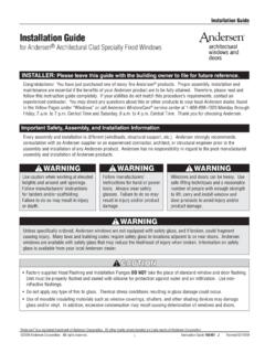
1 FB4C(S,Q)LInstallation InstructionsFAN COIL UNITSFOR R-410A REFRIGERANTSIZES 018 TO 06050 HzNOTE: Read the entire instruction manual before starting OF CONTENTSPAGESAFETY 1 Check 2 Mount 4 Electrical 5 Refrigerant Tubing Connection and Evacuation 6 Refrigerant Flow-Control 7 Condensate 8 9 Sequence of AND PERFORMANCE CONSIDERATIONSI mproper Installation , adjustment, alteration, service, maintenance,or use can cause explosion, fire, electrical shock, or otherconditions which may cause death, personal injury or propertydamage. Consult a qualified installer, service agency, or yourdistributor or branch for information or assistance. The qualifiedinstaller or agency must use factory- authorized kits or accessorieswhen modifying this product.
2 Refer to the individual instructionspackaged with kits or accessories when all local safety codes. Wear safety glasses, protectiveclothing and work gloves. Have a fire extinguisher available. Readthese Instructions thoroughly and follow all warnings or cautionsincluded in literature and attached to the unit. Consult localbuilding codes and the current editions of the National ElectricalCode (NEC) and NFPA safety information. This is the safety-alert you see this symbol on the unit and in instruction manuals,be alert to the potential for personal the signal wordsDANGER,WARNING,andCAUTION. These words are used with the safety- alert the most serious hazards whichwillresult insevere personal injury or hazardswhichcouldresult in personal injury or usedto identify unsafe practices whichmayresult in minor personalinjury or product and property used to highlightsuggestions which will result in enhanced Installation , reliability, OPERATION HAZARDF ailure to follow this warning could result in personal injuryor installing or servicing unit, always turn off all power tounit.
3 There may be more than one disconnect switch. Turn offaccessory heater power if applicable. Lock out and tag switchwith a suitable warning label.!WARNINGCUT HAZARDF ailure to follow this caution may result in personal metal parts may have sharp edges or burrs. Use care andwear appropriate protective clothing and gloves whenhandling !INTRODUCTIONFB4C models are R-410A Fan Coils designed for installationflexibility. These units are designed to meet the low air leakrequirements currently in TXV is used on FB4C(S,Q)L. This valve is a bleed-throughtype and adjustable (if necessary). All FB4C fan coils use amulti-tap ECM motor for efficiency. These units have beendesigned for upflow, downflow (kit required), and units require a field supplied air filter, and are designedspecifically for R-410A refrigerant 50 Hz air conditioners.
4 Theseunits are available for systems of 18,000 through 60,000 BTUhnominal cooling Product Dataliterature for allavailable accessory 1 Check EquipmentUnpack unit and move to final location. Remove carton taking carenot to damage unit. Inspect equipment for damage prior toinstallation. File claim with shipping company if shipment isdamaged or unit rating plate which contains proper installationinformation. Check rating plate to be sure unit matches 2 Mount UnitUnit can stand or lie on floor, or hang from ceiling or wall. Allowspace for wiring, piping, and servicing : When unit is installed over a finished ceilingand/or living area, building codes may require a field- suppliedsecondary condensate pan to be installed under the entire localities may allow as an alternative, the running of aseparate, secondary condensate line.
5 Consult local codes foradditional restrictions or : Nuisance sweating may occur if the unit is installed in ahigh humidity environment with low Upflow InstallationIf return air is to be ducted through a floor, set unit on floor overopening and use 1/8 to 1/4- in (3 to 6 mm) thick fireproof resilientgasket between duct, unit, and return is a field option on slope coil models. Cut opening perdimensions. (See Fig. 1.) A field- supplied bottom closure COILUNITSPOWER ENTRYOPTIONSLOW VOLTENTRYOPTIONSFIELD MODIFIEDSIDE RETURNLOCATION FORSLOPE COILUNITS ONLYFIELD SUPPLIEDRETURN PLENUMUPFLOW/DOWNFLOWSECONDARY DRAINUPFLOW/DOWNFLOWPRIMARY DRAINUNIT 018, 024 030A12" (305 mm)17" (432 mm) " (38 mm) "(64 mm) 19" (483 mm)FIELD SUPPLIEDSUPPLY DUCTUPFLOW/DOWNFLOWSECONDARY DRAINUPFLOW/DOWNFLOWPRIMARY DRAIN018 - 048 21" (533 mm) FRONT SERVICE060 - 060 24" (610mm) CLEARANCEA07565 AFig.
6 1 - Slope Coil Unit in Upflow ApplicationB. Downflow InstallationIn this application, field conversion of the evaporator is requiredusing accessory downflow kit along with an accessory base fireproof resilient gasket, 1/8 to 1/4- in (3 to 6 mm) thick,between duct, unit, and OR PROPERTY DAMAGE HAZARDF ailure to follow this caution may result in product or conversion of the fan coil to downflow requires specialprocedures for the condensate drains on both A-coil and slopeunits. The vertical drains have an overflow hole between theprimary and secondary drain holes. This hole is plugged for allapplications except downflow, but must be used for the conversion process, remove the plastic capcovering the vertical drains only and discard.
7 Remove the plugfrom the overflow hole and discard. At completion of thedownflow Installation , caulk around the vertical pan fitting todoor joint to retain the low air leak performance of the !NOTE: To convert units for downflow applications , refer toInstallation Instructions supplied with kit for proper slope fan coils, use kit Part No. KFADC0201 SLP. For A-coils,use kit Part No. KFADC0401 ACL. Use fireproof resilient gasket,1/8 to 1/4- in (3 to 6 mm) thick, between duct, unit, and : Gasket kit number KFAHD0101 SLP is also required forall downflow applications to maintain low air leak/low Horizontal InstallationUnits must not be installed with access panels facing up or other units are factory built for horizontal left Installation .
8 (SeeFig. 2 and 3.) When suspending unit from ceiling, dimples incasing indicate suitable location of screws for mounting metalsupport straps. (See Fig. 2.)PROPERTY DAMAGE HAZARDF ailure to follow this caution may result in product or optimum condensate drainage performance in horizontalinstallations, unit should be leveled along its length and !For horizontal applications having high return static and humidreturn air, the Water Management Kit, KFAHC0125 AAA, mayneed to be used to assist in water VOLTENTRYOPTIONSPOWERENTRY OPTIONSSECONDARYDRAIN018-048 21" (533 mm)060-060 24" (610 mm) FRONT SERVICECLEARANCE(FULL FACEOF UNIT)SECONDARYDRAINA-COILHORIZONTAL " (44 mm) FILTER ACCESSCLEARANCEA07566 Fig. 2 - Slope Coil Unit in Horizontal Left ApplicationABCFACTORY SHIPPEDHORIZONTAL LEFTAPPLICATIONAIR SEALASSEMBLYHORIZONTALDRAIN PANREFRIGERANTCONNECTIONSSECONDARY DRAINHORIZONTAL LEFTPRIMARY DRAINHORIZONTAL LEFTCOILSUPPORTRAILCOILBRACKETDRAIN PANSUPPORTBRACKETCOILBRACKETA00072 Fig.
9 3 - A- Coil in Horizontal Left ApplicationNOTE: Gasket kit number KFAHD0101 SLP is required forhorizontal slope coil conversion to maintain low air leak/low Remove blower and coil access panel and fitting panel. (SeeFig. 4.)32. Remove coil mounting screw securing coil assembly toright side casing Remove coil Lay fan coil unit on its right side and reinstall coil assemblywith condensate pan down. (See Fig. 4.)5. Attach coil to casing flange using coil mounting screw pre-viously Make sure the pan cap in the fittingdoor is properly seatedon the fittingdoor to retain the low air leak rating of Add gaskets from kit KFAHD per kit Align holes with tubing connections and condensate panconnections, and reinstall access panels and fitting sure liquid and suction tube grommets are in place to preventair leaks and cabinet sweating.
10 Install after MOUNTINGSCREWBLOWER ASSEMBLYREFRIGERANTCONNECTIONSSECONDARY DRAINPRIMARY DRAINDRAINPANSLOPE COILSKICOILSUPPORT RAILA03001 Fig. 4 - Conversion for Horizontal Right ApplicationsHorizontal Right Conversion of Units With A-Coils1. Remove blower and coil access panels. (See Fig. 5.)COILSUPPORTRAILCOILBRACKETDRAIN PANSUPPORTBRACKETCOILSUPPORTRAILCOILBRAC KETHORIZONTALDRAIN PANPRIMARY DRAINHORIZONTAL RIGHTSECONDARY DRAINHORIZONTAL RIGHTREFRIGERANTCONNECTIONSAIR SEALASSEMBLYABCHORIZONTALRIGHTAPPLICATIO NA00071 Fig. 5 - Conversion for Horizontal Right ApplicationsUsing A-Coil2. Remove metal clip securing fitting panel to condensate fitting Remove 2 snap- in clips securing A- coil in Slide coil and pan assembly out of Remove horizontal drain pan support bracket from coil sup-port rail on left side of unit and reinstall on coil support railon right side of unit.