Transcription of Installation Instructions - Cooper Industries
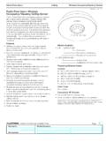
1 Installation InstructionsModel # OAC-P-0500 Model # OAC-P-0500-RModel # OAC-P-1500 Model # OAC-P-1500-RPassive infrared ceiling Mounted LowVoltage Occupancy sensor Read all Instructions on both sides of this sheet first Install in accordance with ALL local codes For indoor use only For Use with Greengate Switchpacks & Systems Only Do not run any Greengate low voltage Wiring in thesame conduit as power conductorsPower Requirements:Input: 10-30 VDC from Greengate Switchpack or Greengatesystem. Maximum current needed is 25mA per sensorOutput: Open collector output to switch up to tenGreengate Switchpacks. BAS with Isolated Form C Relay (-R model) Isolated Form C Relay Ratings: 1A 30 VDC/VACO perating Environment: Temperature: 32 F 104 F (0 C 40 C) Relative Humidity: up to 90% non-condensingThe OAC-P ceiling Mount low voltage Occupancy sensor is a Passive infrared (PIR) motion sensing lighting control, used for energy savings and convenience.
2 The sensor produces a Passive infrared (PIR) motion sensing lighting control, used for energy savings and convenience. When motion is detected, the blue wire is electronicallyconnected to the red wire, energizing the relay in the switchpack to turn ON the load. If vacancy is detected, the bluewire is disconnected from the red, causing the relay to open turning OFF the load. The red lead is 10-30 VDC supply,the black lead is common, and the blue is the relay sensor includes self-adaptive technology that continually adjusts to conditions by adjusting sensitivity andTime Delay in maximum coverage area may vary somewhat according to room shape and the presence of obstacles.
3 Follow thecoverage diagram concerning major and minor motion coverage. The sensor must have a clear view of the area to becontrolled. The sensor will not see through glass. Mounting height should not exceed 12 feet. Optimum mountingheight is 8 to 10 feet. Avoid pointing into hallways. Mounting at fixture height is most effective. *To prevent false activation, the sensor should be mounted away from the air supply duct a minimum of 4 to 6 OAC-P sensor can be mounted to the ceiling , junction box, or round fixture with : Before installing or performing any service on a Greengate system, the power MUST be turned OFF atthe branch circuit breaker. According to NEC 240-83(d), if the branch circuit breaker is used as the main switch fora fluorescent lighting circuit, the circuit breaker should be marked SWD.
4 All installations should be in compliance with the National Electric Code and all state and local codes. NOTE REGARDING COMPACT FLUORESCENT LAMPS: The life of some compact fluorescent lamps (CFLs) is shortenedby frequent automatic or manual switching. Check with CFL and ballast manufacturer to determine the effects of Make sure power is turned OFF at the branch circuit Wire units as shown in wiring diagrams per applicable voltage requirements. (Use twist-on wire connectorsfor all connections) CAP ALL UNUSED WIRE LEADS. 3. Mount unit to ceiling , junction box, or round fixture with Turn power back ON at the branch circuit breaker and wait 2 minutes for the unit to Make necessary adjustments.
5 (See Checkout and Adjustments section)OAC-STEM Threaded Rod(sold separately)Maximum coverage area mayvary somewhat according to roomshape and the presence of NEMA WD 7 Guide and roboticmethod were utilized to verifycoverage Motion, IRMajor Motion, ft( m)10 ft(3 m)5 ft( m)005 ft( m)10 ft(3 m)DT1k020 ft( )3 ft( )15 ft( m)15 ft( m)20 ft( )20 ft( )20 ft( )10 ft(3 m)5 ft( m)10 ft(3 m)5 ft( m)15 ft( m)15 ft( m)OAC-P-1500-R Coverage DiagramMaximum coverage area mayvary somewhat according to roomshape and the presence of NEMA WD 7 Guide and roboticmethod were utilized to verifycoverage Motion, IRMajor Motion, ft( m)03 ft( )5 ft( m)5 ft( m)7 ft( m)7 ft( m)5 ft( m)5 ft( m)7 ft( m)7 ft( m)OAC-P-0500-R Coverage DiagramLoad 1 BlueNeutralHot**Use black lead for 120 VAC Use orange lead for 277 VAC Cap unused **HotWhiteBlueSWITCH-PACK Black Blue Brown Yellow Purple Gray Orange Red White/BrownLoad 2 BlueNeutralHot**Use black lead for 120 VAC Use orange lead for 277 VAC Cap unused **HotWhiteBlueSWITCH-PACK Black (Common)Blue (Control) Red (15 VDC) Black (Common)Blue (Control) Red (15 VDC)Model GMDS - Load 2(Normally OpenMomentary Switch)Model GMDS - Load 1(Normally OpenMomentary Switch)Manual Mode Operation:Switches are required to turn corresponding loads ON.
6 Lights turn OFF when sensor times out or with the Mode Operation: sensor turns ON both switchpacks. Switches can be used to turn lights ON or daylight sensor is enabled and light level is above setpoint, switchpack connected to yellow lead will not turn ON. Recommended Wire:18-3 AWG Stranded Wirenon/shielded. Manual or Automatic-On Control ofTwo Standard SwitchpacksLoadBlueNeutralHot**Use black lead for 120 VAC Use orange lead for 277 VAC Cap unused **HotWhiteBlueSWITCH-PACKTo additional sensors Maximum of 5 sensors per switchpack Black Blue Red Black (Common)Blue (Control) Red (15 VDC)To additional switchpacks Maximum of 10 switchpacks per sensorOne sensor , One SwitchpackSENSOR WIRE LEAD LEGENDB lack (Common)Red (10-30 VDC)Blue (Control - Occupancy)Yellow (Control - Occupancy and Daylight)Brown (Switch-Blue Lead Control)Brown/White (Switch-Yellow Lead Control) sensor 's Isolated RelayOrange (Normally Open)Gray (Common)Purple (Normally Closed)
7 30 m30 m15 m15 mOAC-P-1500 OAC-P-0500P/N 9850-000168-01 Cooper Lighting Solutions 1121 Highway 74 SouthPeachtree City, GA 30269 InformationSpecificationsDescriptionCove rageLocationInstallationWiring9850-00016 8-01_OAC-P_Installation Instructions_Installation sheet 3/28/2014 2:33 PM Page 1 Please refer to under the Legal section for our terms and CausesSuggestionsLights Will NotTurn ON automaticallyWall Switch OFFTurn Wall Switch low voltage switch option is used, lights mayhave been turned-off low- voltage Feature EnabledIf all lights are required to turn ON adjust DIP Switch 10and/or daylight potentiometerPower interruptionCheck incoming voltage and/or wiringLights Will Not Turn ON manuallyDaylight Feature EnabledIf all lights are required adjust DIP switch 10 and/or interruptionCheck incoming voltage and/or wiringIf lights will still not turn ON.
8 Set sensor to override mode and call Technical Services at 1-800-553-3879 Lights Will Not Turn OFF automaticallyOverrideMake sure sensor is not in Override Mode (DIP Switch 8 up). sensor installed close to an air vent Sensors should be installed minimum 4 - 6 feet away fromany air vent and out of path of heavy installed close to indirect should be mounted away from indirect may be possible for the unit to have self-adjusted the timedelay to a 30 minute delay. If the lights do not turn OFF after30 minutes follow next Minute DelayMaximum time delay is 30 Minutes. Check DIP Switches toverify DIP Switch settings. If lights do not turn OFF at the settime delay, check next activated by heat source other than occupantMove DIP Switch 5 wiring to make sure sensor or switchpack are Will Not Turn OFF manuallyOverrideMake sure sensor is not in Override Mode (DIP Switch 8 up).
9 If lights will still not turn OFF, call Technical Services at 1-800-553-3879 LED Indicators FunctionalityAdjustments should be made with the HVAC system ON. Use only insulated tools to make sensor is shipped in the Self-Adjust Mode. This applies to Time Delay and PIR sensitivity. In preparation for theInstaller Test, the time delay is set to 15 seconds, after the sensor is installed, powered-ON and has stabilized, theunit will Time-out 15 seconds after the last motion detected. Coverage and sensitivity can be confirmed by watchingthe Passive infrared (PIR) indicator LEDs on the front of the sensor , while moving around the Walk around the room and monitor LEDs.
10 LEDs should only turn ON for second with each motion. (If LEDsdo not turn ON, go to Installer Adjustments - Sensitivity Adjustments Section)2. Stand still six to eight feet away from the sensor for five seconds. LEDs should not turn ON. (If any LED turnsON, note LED and go to Installer Adjustments Sensitivity Adjustment section)3. Walk outside the room and wait 15 seconds for the lights to turn OFF. (If lights do not turn OFF go to InstallerAdjustments Section)4. Re-enter the room to activate sensor . (If lights do not turn ON go to Troubleshooting Section)5. The unit will remain in Test Mode for 10 minutes then automatically exit Test Mode and go for 10 min.