Transcription of INSTALLATION INSTRUCTIONS - Lennox
1 Page 103/06*2P0306*505,181M*P505181M* 2006 Lennox Industries , Texas, USARETAIN THESE INSTRUCTIONS FOR FUTURE REFERENCEINSTALLATIONINSTRUCTIONSG40UH(X ) SeriesGAS FURNACE505,181M03/2006 Supersedes 505,011 MTable of ContentsUnit Dimensions2.. G40UH(X) Parts Arrangement3.. G40UH(X) Gas Furnace4.. Shipping and Packing List4.. Safety Information4.. General5.. Combustion, Dilution & Ventilation Air5.. Setting Equipment8.. Filters12.. Duct System12.. Venting12.. Gas Piping20.. Electrical21.. Unit Start Up25.. Gas Pressure Adjustment26.. High Altitude Information27.. Other Unit Adjustments27.. Service28.. Repair Parts List30.. Ignition Control Board Diagnostic Codes31.. Troubleshooting32.. Start Up & Performance Check List35.
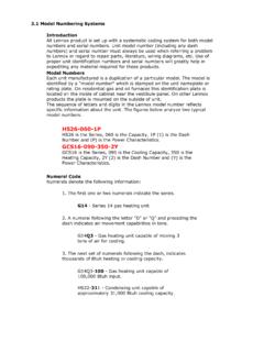
2 WHAT TO DO IF YOU SMELL GAS:Do not store or use gasoline or otherflammable vapors and liquids in thevicinity of this or any other and service must beperformed by a qualified installer,service agency or the gas not try to light any not touch any electrical switch; do notuse any phone in your call your gas supplier from aneighbor s phone. Follow the gas supplier you cannot reach your gas supplier, callthe fire OR EXPLOSION to follow safety warnings exact-ly could result in serious injury, death,or property the building 2G40UH(X) Unit Dimensions inches (mm)*Bottom ReturnAir OpeningGAS PIPING INLET(Either Side)*Side ReturnAir Opening(Either Side)*Bottom ReturnAir OpeningFLUE OUTLET(Top)ELECTRICAL INLET(Either Side)ELECTRICAL INLET(Either Side)SUPPLY AIROPENINGAIR FLOWFRONT VIEWSIDE VIEWTOP VIEWAB9/16 (14)CD3/4 (19)3/4 (19)28 1/2(724)19 7/16(494)23 1/2(597)4 1/4(108) 14 (356) Right13 1/4 (337) Left4 7/8 (124) Right2 1/4 (57) Left40(1016)3 3/4 (95)4(102)1 15/16 (49)23(584)14(356)9/16(14)3 3/4(95)3 1/4 (83) Right8 1/8 (206)
3 Left**FLUE OUTLET(Either Side)TOP VIEW OPTIONALEXTERNALSIDE RETURNAIR FILTER KIT(Either Side)16(406)14 3/4(375)5/8 (16) OPTIONALEXTERNALSIDE RETURNAIR FILTER KIT(Either Side)23-3/4 (603)25 (635)**Flue outlet may be horizontal but furnace must bevented vertically Optional external side return air filter kit cannot be usedwith the optional RAB Return Air Base.*NOTE 60C and 60D units that require air volumesover 1800 cfm (850 L/s) must have one of the following:1. Return air from single side with transition which will accommodate 20 x 25 x 1 in. (508 x 635 x 25 mm) cleanable air filter. (Required to maintain proper air velocity.)2. Return air from single side with optional RAB Return Air Return air from Return air from both Return air from bottom and one to Engineering Handbook for additional NoABCDM odel 24A 045,G40UH 24A 070,G40UH 36A 045,G40UH 36A 07014 1/236813 3/8340133304 1/2114G40UH 36B 090,G40UH 48B 070,G40UH 48B 09017 1/244616 3/8416164066152G40UH 36B 110,G40UH 48C 110,G40UH 48C 135,G40UH 60C 1102153319 7/845419 1/24957 3/4197G40UH 60D 135G40UH 60D 15524 1/262223 3/8546235849 1/2241 Page 3G40UH(X)
4 Parts ArrangementFIGURE 1 Flue TransitionCombustion Air InducerCombustion AirOrificeCombustion AirPressure SwitchFlue Collector BoxHeat ExchangerFlame SensorGas ValveBurnersIgniterNOx InsertPrimary LimitBlower AssemblyCapacitorDoor Interlock SwitchIntegrated IgnitionControl BoardControl TransformerGasketFlue Box GasketFlame Rollout Switches*Flame Rollout BracketGas OrificesIgniter BracketBurner Bottom ShieldLimit ShieldSecondary Limit(NOx Units Only)Air DeflectorG40UH 48C 135,G40UH 60C 110, &G40UH 60D 155 Units Only*135 and 155 kBtuh units only Flame rollout switches are locatedon brackets on the inner sides (oneon the left and one on the right) ofthe burner 4G40UH(X) Gas FurnaceThe G40UH(X) gas furnace is shipped ready for installa-tion in the upflow and horizontal position (left or right)fueled by natural gas.
5 A conversion kit (ordered separate-ly) is required for use in propane/LP gas applications. Thefurnace is shipped with the bottom panel in place. The bot-tom panel must be removed if the unit is to be installed in ahorizontal application. The panel may also be removed inupflow and Packing ListPackage 1 of 1 contains1 Assembled G40UH(X) unit1 Bag assembly containing the following:2 Screws3 Wire nuts1 Snap bushing1 Snap plug1 Wire tie1 Vent warning label1 Owner s manual and warranty cardThe following items may also be ordered separately:1 Thermostat1 Hanging bracket (for horizontal installations)1 Propane/LP changeover kitCheck equipment for shipping damage. If you find anydamage, immediately contact the last InformationWARNINGI mproper INSTALLATION , adjustment, alteration, serviceor maintenance can cause property damage, person-al injury or loss of life.
6 INSTALLATION and service mustbe performed by a qualified installer, service agencyor the gas with any mechanical equipment, personal injurycan result from contact with sharp sheet metaledges. Be careful when you handle this (X) units are CSA International certified to and CSA the USA, INSTALLATION of gas furnaces must conform with lo-cal building codes. In the absence of local codes, units mustbe installed according to the current National Fuel Gas Code( ). The National Fuel Gas Code is availablefrom the following address:American National Standards Institute, West 42nd StreetNew York, NY 10036In Canada, INSTALLATION must conform with current CSAB149 Natural Gas and Propane INSTALLATION Codes, localplumbing or waste water codes and other applicable clearance must be made around the air open-ings into the vestibule area.
7 In order to ensure proper unitoperation, combustion and ventilation air supply must beprovided according to the current National Fuel Gas Codeor CSA B149 installations must be consistent with the ventingtables (in this instruction) and applicable provisions of localbuilding furnace is CSA International certified for installationclearances to combustible material as listed on the unitnameplate and in the tables in figures 6 and 11. Accessibilityand service clearances must take precedence over fireprotection For INSTALLATION on combustible floors, the furnaceshall not be installed directly on carpeting, tile, or othercombustible material other than wood INSTALLATION in a residential garage, the furnace mustbe installed so that the burner(s) and the ignition sourceare located no less than 18 inches (457 mm) above thefloor.
8 The furnace must be located or protected to avoidphysical damage by vehicles. When a furnace is installedin a public garage, hangar, or other building that has a haz-ardous atmosphere, the furnace must be installed accord-ing to recommended good practice requirements and cur-rent National Fuel Gas Code or CSA B149 Furnace must be adjusted to obtain a temperaturerise within the range specified on the unit nameplate. Failureto do so may cause erratic limit operation and premature heatexchanger G40UH(X) furnace must be installed so that its electri-cal components are protected from this furnace is used with cooling units, it shall beinstalled in parallel with, or on the upstream side of, coolingunits to avoid condensation in the heating a parallel flow arrangement, a damper (or other meansto control the flow of air) must adequately prevent chilled airfrom entering the furnace.
9 If the damper is manually oper-ated, it must be equipped to prevent operation of either theheating or the cooling unit, unless it is in the full HEAT orCOOL installed, this furnace must be electrically groundedaccording to local codes. In addition, in the United States, INSTALLATION must conform with the current National ElectricCode, ANSI/NFPA No. 70. The National Electric Code(ANSI/NFPA No. 70) is available from the following ad-dress:National Fire Protection Association1 Battery March ParkQuincy, MA 02269In Canada, all electrical wiring and grounding for the unitmust be installed according to the current regulations of theCanadian Electrical Code Part I (CSA Standard )and/or local 5 NOTE This furnace is designed for a minimum continu-ous return air temperature of 60 F (16 C) or an intermit-tent operation down to 55 F (13 C) dry bulb for caseswhere a night setback thermostat is used.
10 Return air tem-perature must not exceed 85 F (29 C) dry G40UH(X) series units should not be installed asa unit G40UH(X) furnace may be installed in alcoves, clos-ets, attics, basements, garages, and utility rooms in the up-flow or horizontal furnace design has not been CSA International certi-fied for INSTALLATION in mobile homes, recreational vehicles,or does not recommend the use of G40UH(X) units asa construction heater during any phase of low return air temperatures, harmful vapors and op-eration of the unit with clogged or misplaced filters will dam-age the (X) units may be used for heating of buildings orstructures under construction, if the following conditionsare met:DThe vent system must be permanently installed perthese INSTALLATION room thermostat must control the furnace.