Transcription of INSTALLATION INSTRUCTIONS - Lennox
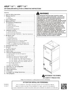
1 2017 Lennox Industries Inc. Dallas, Texas, USAPage 1 WARNINGThis product contains a chemical known to the State of California to cause cancer, birth defects, or other reproductive harm. WARNINGI mproper INSTALLATION , adjustment, alteration, service or maintenance can cause property damage, personal injury or loss of life. INSTALLATION and service must be performed by a licensed professional HVAC installer or equivalent, service agency, or the gas supplier. IMPORTANTThe Clean Air Act of 1990 bans the intentional venting of refrigerant (CFCs, HCFCs and HFCs) as of July 1, 1992. Approved methods of recovery, recycling or reclaiming must be followed. Fines and/or incarceration may be levied for INSTRUCTIONSMULTI- position AIR HANDLERS507674-013/2017 Elite Series CBA27 UHE Air Handler UnitsTHIS MANUAL MUST BE LEFT WITH THE HOMEOWNER FOR FUTURE REFERENCEIMPORTANT: Special procedures are required for cleaning the all-aluminum coil in this unit.
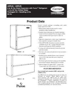
2 See page 15 in this instruction for INFORMATION FOR INSTALLERTOP CAP SHIPPINGBRACKET (REPLACESCREWS IN TOP CAPAFTER REMOVAL)HORIZONTAL DRAIN PAN (SEE PAGES 4 AND 6)BLOWER HOUSINGSUPPORT PADREFRIGERANT LINE PLUGS(SEE PAGE 6)DRIP SHIELD. (USED FOR -060 UNITS HORIZONTALAPPLICATIONS ONLY.) (SEE PAGE 5.) SHOWNINSTALLED ON DRAIN PAN IN -060 FOR AND REMOVE THESE ITEMS BEFORE OPERATING of ContentsCBA27 UHE Upflow and Downflow Unit Dimensions ..2 CBA27 UHE Horizontal Left- and Right-Hand Discharge Unit Dimensions ..3 General Information ..4 Shipping and Packing List ..4 Requirements ..4 Installing the Unit ..4 Brazing Connections ..6 Installing the Condensate Drain ..7 Inspecting and Replacing Filters ..8 Sealing the Unit ..8 Measuring Static Pressure ..9 Adjusting the Blower Speed ..9 Making Electrical Connections ..12 Repairing or Replacing Cabinet Insulation.
3 15 Homeowner Maintenance ..15 Check-Out Procedures ..16 Page 2 OPTIONALELECTRIC HEAT(FIELD-INSTALLED)AIRFLOWLIQUIDLINESU CTIONLINESUPPLY AIROPENINGRETURN AIRFILTERLOW VOLTAGEINLETS (TOP ANDRIGHT SIDE)RETURN AIRTOP VIEWFRONT VIEWSIDE VIEWBLOWERPIPING PLATE DETAIL(FOR UP-FLOW AND DOWN-FLOW POSITIONS)ACB11 1/16 (281)DFELIQUID LINESUCTION LINECONDENSATE DRAINS(2) (HORIZONTAL)COIL3/4 (19)3/4 (19)5/8 (16))52( 1)61( 8/55/8 (16)1 3/4 (44)2(51)1 1/8 (29)4 3/8 (111)2 3/4(70)5 3/8(137)3 1/2 (89)OPTIONALELECTRIC HEAT(FIELD-INSTALLED)AIR FLOWLIQUIDLINESUCTIONLINER eturnAir OpeningSUPPLYAIRFILTERSUPPLY AIRTOP VIEWFRONT VIEWSIDE VIEWBLOWERABC11 1/16 (281)FDECOIL5/8 (16)5/8 (16)5/8 (16)5/8 (16)5/8 (16)LOW VOLTAGE(RIGHT SIDE)LINE VOLTAGE(LEFT SIDE)DOWN-FLOW POSITION1 (25)UP-FLOW POSITIONCONDENSATE DRAINS(2) (UP-FLOW ANDDOWN-FLOW)FILTER ACCESSFILTER ACCESSHGHGLINE VOLTAGEINLETS (TOPAND LEFT SIDE)5/8 (16)5/8 (16)
4 CBA27 UHE Common Dimensions - Inches (mm) (1251)51 (1295)58-1/2 (1486)62 1/2 (1588)B21-1/4 (540)21-1/4 (540)21 1/4 (540)21 1/4 (540)C20-5/8 (524)22 5/8 (575)24-5/8 (625)24-5/8 (625)D19-3/4 (502)19-3/4 (502)19 3/4 (502)19 3/4 (502)E19 (483)21 (533)23 (584)23 (584)F20 (508)20 (508)20 (508)20 (508)G24-5/8 (625)26 3/8 (670)27 7/8 (708)27 7/8 (708)H24-5/8 (625)24-5/8 (625)30-5/8 (778)34 5/8 (879)CBA27 UHE Upflow and Downflow Unit Dimensions Inches (mm) Page 3 LIQUIDLINESUCTIONLINES upplyAirOpeningFILTERLOW VOLTAGEINLETS (BOTTOMAND RIGHTSIDE)TOP VIEWFRONT VIEWBLOWERHBCDLIQUIDLINESUCTIONLINECONDE NSATEDRAINS (2)(UP-FLOWANDDOWN-FLOW)CONDENSATEDRAINS (2)(HORIZONTAL)Coil3/4 (19)3/4 (19)1 1/2(38)1 3/4(44)5 3/4(46)2(51)1 1/8(29)RETURN AIROPENINGFE5/8 (16)5/8 (16)5/8 (16)END VIEWAIRFLOWOPTIONAL ELECTRICHEAT (FIELD-INSTALLED)11 1/16(281)LINE VOLTAGEINLETS (TOPAND RIGHTSIDE)5 3/8(137)4 3/8(111)LIQUIDLINESUCTIONLINES upplyAir OpeningFILTERLOW VOLTAGEINLETS (TOP ANDLEFT SIDE)END VIEWBLOWERBCDCoil3/4 (19)3/4 (19)3/4 (19)ReturnAir OpeningFE5/8 (16)5/8 (16)5/8 (16)END VIEWAir FlowOPTIONAL ELECTRICHEAT (FIELD INSTALLED)LINE VOLTAGE INLETS(BOTTOM AND LEFT SIDE)Horizontal position (Right Hand AirDischarge)FILTER ACCESSFILTER ACCESS5 3/4(146)1 1/2 (38)1 3/4(44)CONDENSATE DRAINS (2)(HORIZONTAL)A5/8 (16)GHA5/8 (16)G1 (25)1 (25)11 1/16(281)PIPING PLATEDETAILLIQUIDLINESUCTION LINE2(51)1 1/8(29)5 3/8(137)4 3/8(111)PIPING PLATEDETAILH orizontal position (Left Hand AirDischarge)TOP VIEWFRONT VIEW3/4 (19)END VIEWFOR DIMENSIONS A THROUGH H , SEE CHART ON PAGE Horizontal Left- and Right-Hand Discharge Unit Dimensions Inches (mm)
5 Page 4 CAUTIONAs with any mechanical equipment, contact with sharp sheet metal edges can result in personal injury. Take care while handling this equipment and wear gloves and protective Information The Elite CBA27 UHE series air handler with all-alumi-num coil is designed for INSTALLATION with optional field-in-stalled electric heat and a matching HFC-410A outdoor instruction is intended as a general guide and does not supersede local or national codes in any way. Consult authorities having jurisdiction before INSTALLATION . Shipping and Packing List Package 1 of 1 contains: 1 Assembled air handler unit 1 Horizontal drip shield (CBA27 UHE-060 only) 1 Pipe nipple (Sch80, 3/4" x 5"1 Warranty card NOTE For downflow applications, order kit number the air handler for shipping damage; if found, im-mediately contact the last carrier.)
6 Requirements IMPORTANTThis unit must be matched with an indoor coil as specified in the Lennox Engineering Handbook. Coils previously charged with HCFC-22 must be addition to conforming to manufacturer s INSTALLATION in-structions and local municipal building codes, INSTALLATION of Lennox air handler units (with or without optional elec-tric heat), shall conform with the following National Fire Protection Association (NFPA) standards: NFPA No. 90A - Standard for INSTALLATION of Air Condi-tioning and Ventilation Systems NFPA No. 90B - Standard for INSTALLATION of Residence Type Warm Air Heating and Air Conditioning SystemsThis unit is approved for INSTALLATION clearance to combus-tible material as stated on the unit rating plate. Accessi-bility and service clearances must take precedence over combustible material the Unit These units are factory-configured for upflow and hori-zontal right-hand discharge INSTALLATION .
7 For downflow or horizontal left-hand discharge, certain field modifications are AIR HANDLER UNITSThe air handler units consists of two factory-assembled sections. It may be necessary to disassemble the sections when positioning the unit for disassemble:1 - Remove access - Remove both blower and coil assemblies. This will lighten the cabinet for - Remove one screw from the left and right posts inside the unit. Remove one screw from each side on the back of the unit. Unit sections will now reassemble:1 - Align cabinet sections - Reinstall - Replace blower and coil - Replace access APPLICATIONUse the following procedures to configure the unit for up-flow operations:1 - Remove access - Remove and discard the horizontal drip shield (-060 model, used only on horizontal applications) and the corrugated padding between the blower and coil - The horizontal drain pan must be removed when the coil blower is installed in the upflow position .
8 Removing the horizontal drain pain will allow proper air flow and increased - After removing the horizontal drain pan, place the unit in the desired location. Set unit so that it is level. Connect return and supply air plenums as required using sheet metal screws as illustrated in figure - Install units that have no return air plenum on a stand that is at least 14" from the floor to allow for proper air return. Lennox offers an optional upflow unit stand as listed in table DRAIN PAN (MUST BE REMOVED)UP-FLOW /DOWN-FLOWDRAIN PANFIGURE 1. Upflow Configuration TABLE 1. Optional Side-Return Unit Stand (Upflow Only)ModelKit NumberAll unit sizes45K32 Page 5 HORIZONTAL RIGHT-HAND DISCHARGE APPLICATIONUse the following procedures to configure the unit for hor-izontal right-hand discharge operations:NOTE For horizontal applications, a secondary drain pan is recommended.
9 Refer to local - Before operating the unit, remove access panels and the horizontal drip shield (-060 model) and the corrugated padding between the blower and coil assembly. Discard the corrugated - Install the horizontal shield on the front edge of the horizontal drain pan as illustrated in figure - No further adjustment is necessary. Set unit so that it is sloped 1/4" towards the drain pan end of the - If the unit is suspended, the entire length of the cabinet must be supported. If you use a chain or strap, use a piece of angle iron or sheet metal attached to the unit (either above or below) to support the length of the cabinet. Use securing screws no longer than 1/2" to avoid damaging the coil or filter as illustrated in figure 3. Use sheet metal screws to connect the return and supply air plenums as / DOWN-FLOWDRAIN PANHORIZONTAL DRIP SHIELD (-060 MODELS)DOWN-FLOW RAILHORIZONTAL DRAIN PANNO ADJUSTMENT IS NECESSARYFIGURE 2.
10 Right-Hand Discharge Configuration HORIZONTAL RIGHT-HAND DISCHARGE APPLICATION IN HIGH-HUMIDITY AREASFor horizontal applications in high humidity areas, remove the downflow rail closest to the drain remove rail:1 - Remove the screws from the rail at the back of unit and at the cabinet support - Remove the downflow rail then replace - Seal around the exiting drain pipe, liquid line, and suction line to prevent humid air from infiltrating into the VIEWEND VIEWANGLE IRON ORSHEET METALELECTRICAL INLET CLEARANCE 4"(102 mm) 1/2" SCREWS MAXIMUMFIGURE 3. Suspending Horizontal Unit IMPORTANTWhen removing the coil, there is possible danger of equipment damage and personal injury. Be careful when removing the coil assembly from a unit installed in right- or left-hand applications. The coil may tip into the drain pan once it is clear of the cabinet.