Transcription of INSTALLATION INSTRUCTIONS - Power Sentry
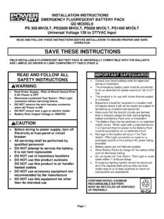
1 INSTALLATION INSTRUCTIONS ! IMPORTANT SAFEGUARDS !WHEN USING ELECTRICAL EQUIPMENT, BASIC SAFETY PRECAUTIONS SHOULD ALWAYS BE FOLLOWED, INCLUDING THE FOLLOWING:READ AND FOLLOW ALL SAFETY INSTRUCTIONS 1. To prevent high voltage from being present on red & yellow output leads prior to INSTALLATION , inverter connector must be open. Do not join inverter connector until INSTALLATION is complete and AC Power is supplied to the emergency ballast. 2. This product is for use with one 17 W through 215 W (2' - 8') or two 17 W through 40 W (2' - 4') single pin or bipin fluorescent lamps, including standard, energy saving, HO, VHO, circline, U-shaped and rapid-start (4-pin) Long compact fluorescent lamps.
2 3. Make sure all connections are in accordance with the National Electrical Code and any local regulations. 4. To reduce the risk of electric shock, disconnect both normal and emergency Power supplies and inverter connector of the emergency ballast before servicing. 5. This emergency ballast is for factory or field INSTALLATION in either the ballast channel or on top of the fixture. 6. This product is suitable for use in damp locations where the ambient temperature is 0 C minimum, +50 C maximum. Product is also suitable for INSTALLATION in sealed and gasketed fixtures. Product is not suitable for heated air outlets and wet or hazardous locations.
3 7. An unswitched AC Power source is required (120 through 277 VAC, 50/60 Hz). 8. Do not install near gas or electric heaters. 9. Do not attempt to service the battery. A sealed, no-maintenance battery is used that is not field replaceable. Contact the manufacturer for information on service. 10. The use of accessory equipment not recommended by the manufacturer may cause an unsafe condition. 11. Do not use this product for other than intended use. 12. Servicing should be performed by qualified service THESE INSTRUCTIONS05/13/11 Power Sentry /ACCUPRO 1400 Lester Road, Conyers, Georgia 30012 Tech Support 1-888-300-7017 E7144675000205PS1400 MVOLTNi - CdCONTAINS NICKEL-CADMIUMRECHARGEABLE BE RECYCLED OR DISPOSED OF : Make sure the necessary branch circuit wiring is available.
4 An unswitched source of Power is required. The emergency ballast must be fed from the same branch circuit as the AC ballast. 1. Disconnect AC Power from the fixture. Remove the ballast channel cover and install the emergency ballast either in the ballast channel (see Illustrations 1&2) or on top of the fixture* (see Illustration 3). 2. Select the appropriate wiring diagram to connect the emergency ballast to the AC ballast and lamp. Make sure all connections are in accordance with the National Electrical Code and any local regulations. 3. Install the test switch through the ballast channel cover of a troffer or through the side of a strip fixture.
5 Drill a 1/2" hole and install the switch as shown (see Illustration 1&2). Wire the test switch so that it removes AC Power from both the emergency ballast and the AC ballast at the same time (see Illustration 4). 4. Refer to Illustration 5 and install the charging indicator light so that it will be visible after the fixture is installed. 5. In a readily visible location, attach the label CAUTION This Unit Has More Than One Power Connection Point. To Reduce The Risk Of Electric Shock, Disconnect Both The Branch Circuit-Breakers Or Fuses And Emergency Power Supplies Before Servicing. WARNING: TO PREVENT HIGH VOLTAGE FROM BEING PRESENT ON RED AND YELLOW OUTPUT LEADS PRIOR TO INSTALLATION , INVERTER CONNECTOR MUST BE OPEN.
6 DO NOT JOIN INVERTER CONNECTOR UNTIL INSTALLATION IS COMPLETE AND AC Power IS SUPPLIED TO THE EMERGENCY 2 ILLUSTRATION 4 UNSWITCHED FIXTURESWITCHED FIXTUREILLUSTRATION 1 ILLUSTRATION 3 NOTE: After installing the charging indicator light and test switch, mark each with the appropriate label. If a detached charging indicator light is used, connect by matching wire colors and install as shown in Illustration POLE OPTION*For INSTALLATION on top of the fixture, wire bundle covers may be required by state or local codes. These covers are available from themanufacturer as an accessory kit and must be ordered separately. Call your local distributor or the factory for complete BALLASTWHITEWHT/BLKHOTCOMACBALLASTWHT/RE DWHITEBLACK EMERGENCY BALLASTWHT/BLKWHT/REDWHITEBLKREDREDBLKTE ST SWITCHBLKBLKTEST SWITCHREDREDBLACK 6.
7 After INSTALLATION is complete, supply AC Power to the emergency ballast and join the inverter connector. 7. A short-term discharge test may be conducted after the emergency ballast has been charging for one hour. Charge for 24 hours before conducting a long-term discharge test. Refer to normal operation AC Power is applied, the charging indicator light is illuminated, indicating that the battery is being charged. When Power fails, the emergency ballast automatically switches to emergency Power (internal battery), operating either one or two lamps for a minimum of 90 minutes. When AC Power is restored, the emergency ballast returns to the charging mode and delays AC ballast operation for approximately three seconds to prevent false-tripping of AC ballast (end-of-lamp-life) shutdown no routine maintenance is required to keep the emergency ballast functional, it should be checked periodically to ensure that it is working.
8 The following schedule is recommended: 1. Visually inspect the charging indicator light monthly. It should be illuminated. 2. Test the emergency operation of the fixture at 30-day intervals for a minimum of 30 seconds. Either one or two lamps should operate at reduced illumination. 3. Conduct a 90-minute discharge test once a year. Either one or two lamps should operate at reduced illumination for at least 90 ANY SERVICING INDICATED BY THESE CHECKS TO QUALIFIED 5 NOTE: After installing the charging indicator light and test switch, mark each with the appropriate STYLE FIXTURESTRIP STYLE FIXTUREC hargingIndicatorLight1/2" WhiteBushingViolet (+) Brown( )Violet (+) Brown( )1/2" WhiteBushing5/8" BlackBushing5/8" BlackBushing1/2" PunchFixtureFixtureChargingIndicatorLigh tWIRING DIAGRAMSThe following diagrams are typical schematics only.
9 May be used with other ballasts. Consult the factory for other wiring diagrams. Emergency Ballast and AC Ballast must be fed from the SAME BRANCH 1 LAMP(DIAMETER)BASETYPEWATTAGE(Length)NO. of LAMPS(EMERGENCY-MODE)BROWNCONNECTORT8,T9 ,T10,T12(1 , 1 , 1 ) SingleorBipin17 - 40 W(2'-4')1 CLOSED2 OPEN40 - 215 W(5' -8')1 OPENLONG COMPACT4-PIN (2G11)18 - 39 W1 CLOSED2 OPEN40 - 55 W1 CLOSEDEMERGENCY BALLAST AND AC BALLAST MUST BE FED FROM THE SAME BRANCH SCHEMATICS ONLY. MAY BE USED WITH OTHER BALLASTS. CONSULT THE FACTORY FOR OTHER WIRING DIAGRAMSWIRING DIAGRAMS for 1-LAMP emergency operation4 FIG D TWO (2) LAMP INSTANT START BALLASTFIG B ONE (1) LAMP INSTANT START BALLASTFIG A ONE (1) LAMP RAPID START BALLASTFIG C TWO (2) LAMP RAPID START BALLASTEMERGENCYBALLASTWALL SWITCHWHT/REDREDWHITEVIOLET (+)BROWN (-)WHITEWHT/BLKCOMMONTESTSWITCHINVERTERC ONNECTORCHARGINGINDICATORBLKBLKHOTLAMP1 LAMPRAPID STARTBALLASTWARNING.
10 Refer to Table 1 before connectingBLUEBLUEBROWNBROWNREDYELLOWYEL /BLKBLU/WHTBLUEREDREDBLACKWHITEEMERGENCY BALLASTWALL SWITCHWHT/REDREDWHITEVIOLET (+)BROWN (-)WHITEWHT/BLKCOMMONTESTSWITCHINVERTERC ONNECTORCHARGINGINDICATORBLKBLKHOTLAMP1 LAMPINSTANTSTARTBALLASTWARNING: Refer to Table 1 before connectingBLUEBLACKWHITEBROWNBROWNREDYEL LOWYEL/BLKBLU/WHTBLUEREDEMERGENCYBALLAST WALL SWITCHWHT/REDREDWHITEVIOLET (+)BROWN (-)WHITEWHT/BLKCOMMONTESTSWITCHINVERTERC ONNECTORCHARGINGINDICATORBLKBLKHOT2 LAMPRAPID STARTBALLASTBLUEBLUEBLACKWHITEREDYELLOWY EL/BLKREDREDYELLOWYELLOWBLU/WHTBLUELAMP 2 LAMP 1 ()EMERGENCYWARNING: Refer to Table 1 before connectingBROWNBROWNEMERGENCYBALLASTWALL SWITCHWHT/REDREDWHITEVIOLET (+)BROWN (-)WHITEWHT/BLKCOMMONTESTSWITCHINVERTERC ONNECTORCHARGINGINDICATORBLKBLKHOTLAMP 1 LAMP 22 LAMPINSTANTSTARTBALLASTWARNING.