Transcription of INSTALLATION INSTRUCTIONS R 410A Ductless Split …
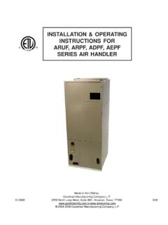
1 421 01 9220 00 10/01/12 INSTALLATION INSTRUCTIONSR 410a Ductless Split SystemAir Conditioner and Heat PumpMODELS: DLC4(A/H) Outdoor, DLF4(A/H) IndoorSIZES: 9K, 12K, 18K, 24K, 30K, and 36 KNOTE: Read the entire instruction manual before starting the OF CONTENTSPAGEPARTS UNIT Mounting Hole in Wall for Connecting Piping,Drain&Wiring..9 OUTDOOR UNIT and Drainage and Power Wiring from Outdoor PURGING AND LEAKAGE FILTER following parts are included in your indoor unit. Pleasecontact your dealer if any parts are damaged or Plate1 Remote Control1 Remote Control Holder1 Mounting Hardware7 Battery ( )2 SAFETY CONSIDERATIONSI nstalling, starting up, and servicing air conditioningequipment can be hazardous due to system pressures,electrical components, and equipment location (roofs,elevated structures, etc.).Only trained, qualified installers and service mechanicsshould install, start up, and service this personnel can perform basic maintenancefunctions such as cleaning coils.
2 All other operations shouldbe performed by trained service working on the equipment, observe precautions in theliterature and on tags, stickers, and labels attached to all safety codes. Wear safety glasses and workgloves. Keep quenching cloth and fire extinguisher nearbywhen brazing. Use care in handling, rigging, and settingbulky these INSTRUCTIONS thoroughly and follow all warningsor cautions included in literature and attached to the local building codes and National Electrical Code(NEC) for special requirements. In Canada, refer to currenteditions of the Canadian Electrical Code, CSA Recognize safety information. This is the safety alertsymbol !!. When you see this symbol on the unit and ininstructions or manuals, be alert to the potential for these signal words: DANGER,WARNING, and CAUTION. These words are used with thesafety alert symbol.
3 DANGER identifies the most serioushazards which will result in severe personal injury or signifies hazards which could result in personalinjury or death. CAUTION is used to identify unsafepractices which may result in minor personal injury orproduct and property damage. NOTE is used to highlightsuggestions which will result in enhanced INSTALLATION ,reliability, or operation.!WARNINGELECTRICAL SHOCK HAZARDF ailure to follow this warning could result in personalinjury or installing, modifying, or servicing system, mainelectrical disconnect switch must be in the OFFposition. There may be more than 1 disconnect out and tag switch with a suitable warning !EQUIPMENT DAMAGE HAZARDF ailure to follow this caution may result in equipmentdamage or improper not bury more than 36 in. (914 mm) of refrigerantpipe in the ground. If any section of pipe is buried, theremust be a 6 in.
4 (152 mm) vertical rise to the valveconnections on the outdoor units. If more than therecommended length is buried, refrigerant may migrateto the cooler buried section during extended periods ofsystem shutdown. This causes refrigerant slugging andcould possibly damage the compressor at start INSTRUCTIONS R 410a Ductless Split System: DLF4(A/H), DLC4(A/H)2 421 02 9220 00 GENERALT hese INSTRUCTIONS cover the INSTALLATION , start up and servicingof DLC4(A/H) outdoor and DLF4(A/H) indoor units REQUIREMENTSA llow sufficient space for airflow and servicing unit. See Figure. 1for minimum required distances between unit and walls : Both refrigerant lines must be Minimum refrigerant line length between the indoor and outdoorunits is 10 ft.
5 (3 m).S The following maximum lengths are allowed:REFRIGERANT LINE LENGTHS ft. (m)Unit SizeMax LineLengthMax Elevation(ID over OD)Max Elevation(OD over ID)9K50 (15)33 (10)33 (10)12K66 (20)33 (10)33 (10)18, 24K82 (25)33 (10)33 (10)30, 36K98 (30)33 (10)33 (10)S The following are the piping SIZESUnit SizeMix PhaseVapor9, 12K1/4 3/8 18K1/4 1/2 24, 30, 36K1/4 5/8 R 410a Refrigerant Charge TableUnit SizeCharge Amount *LBS (kg)Additional Charge Amount **oz/ft (g/m)Metering Device **Cool OnlyHeat PumpCool OnlyHeat ( ) ( ) (15) (20) ( ) ( ) (15) (20) ( ) ( ) (15) (20) ( ) ( ) (15) (50)EXV30K ( ) (50) ( ) ( ) (50) (50)EXV* Charge is for piping that runs up to 25 ft. ( m)** For piping runs greater than 25 ft. ( m), add this amount of charge per foot of extra piping, up to the allowable length, specified in the above table.** EXV Electronic Expansion DeviceConnecting (Power and Control Cable)S The main power is supplied to the outdoor unit.
6 The fieldsupplied connecting cable from the outdoor unit to indoor unitconsists of four wires and provides the power for the indoor unitas well as the communication signal and ground between theoutdoor and indoor unit. Two wires are high voltage AC power, one is low voltage DCsignal and one is a ground Consult local building codes, NEC (National Electrical Code) orCEC (Canadian Electrical Code) for special !EQUIPMENT DAMAGE HAZARDF ailure to follow this caution may result in equipmentdamage or improper Based on the MCA s in the electrical table, only 14 AWGwire should be Use copper conductors only with a minimum 300 voltrating and 2/64 inch thick !EQUIPMENT DAMAGE HAZARDF ailure to follow this caution may result in equipmentdamage or improper Be sure to comply with local codes while running wire fromindoor unit to outdoor Every wire must be connected firmly. Loose wiring maycause terminal to overheat or result in unit malfunction.
7 Afire hazard may also exist. Therefore, be sure all wiring istightly No wire should be allowed to touch refrigerant tubing,compressor or any moving Disconnecting means must be provided and shall belocated within sight and readily accessible from the Connecting cable with conduit shall be routed throughhole in the conduit Data TableUnitSizeSystem VoltageVolts Ph. FanIndoor FanMCAMax Fuse/CB Amps(MOCP)RLALRAFLAO utputWattsVoltsFLAHPO utputWatts(Min/Max)9K115 1 60103 V 1 60103 V 1 60187 V 1 60187 V 1 60187 375 V 1 60187 V 1 60187 V INSTRUCTIONS R 410a Ductless Split System: DLF4(A/H), DLC4(A/H)421 01 9220 003 MODEL NOMENCLATUREMODEL SERIESDLC4AV09J1 APosition Number1234567891011 DLC = OutdoorDLF = IndoorOutdoor/Indoor4AV = AC Outdoor4AC = AC Indoor4HV = HP Outdoor4HH = HP IndoorType09 = 9k BTU12 = 12k BTU18 = 18k BTU24 = 24k BTU30 = 30k BTU36 = 36k BTUSizeJ = 115 1 60K = 208/230 1 60 Voltage1 AFactory DesignationDIMENSIONS INDOORWDHA12377 Unit SizeWIn.
8 (mm)HIn. (mm)DIn. (mm)Net Operating WeightLbs. (Kg) (846) (272) (180)29 (13) (846) (272) (180)29 (13) (940) (297) (201)29 (13) (1008) (315) (218)35 (16) (1349) (325) (54) ( ) (1349) (325) (54) ( ) INSTALLATION INSTRUCTIONS R 410a Ductless Split System: DLF4(A/H), DLC4(A/H)4421 01 9220 00 DIMENSIONS OUTDOORUNIT SIZE (541)(Net Operating Weight: 96 44 kg.)A12380in. (mm)10( )30( )) ( ) ( ) ( ) ( ) ( )UNIT SIZE 12(Net Operating Weight: 107 49 kg.)A12381 INSTALLATION INSTRUCTIONS R 410a Ductless Split System: DLF4(A/H), DLC4(A/H)421 01 9220 ( )35( ) ( )22( ) ( ) ( ) ( )in. (mm)UNIT SIZE 18(Net Operating Weight: 99 45 kg.) ( ) ( ) ( )36( )24( ) ( ) ( )in. (mm)UNIT SIZE 24(Net Operating Weight: 121 55 kg.)A12383 INSTALLATION INSTRUCTIONS R 410a Ductless Split System: DLF4(A/H), DLC4(A/H)6421 01 9220 ( )36( )24( ) ( ) ( ) ( ) ( )in.
9 (mm)UNIT SIZE 30 (Net Operating Weight: 154 lbs 70 kg.)36 (Net Operating Weight: 161 lbs 73 kg.)A12379 INSTALLATION INSTRUCTIONS R 410a Ductless Split System: DLF4(A/H), DLC4(A/H)421 01 9220 007 CLEARANCESD istance to Ceiling6 (152 mm)Distance to Wall6 (152 mm)Distance to Floor66 (1676 mm)Distance to Wall6 (152 mm)Clearance in front of unit118 (2997 mm)Distance toBack Wall12 (305 mm)Air Discharge Side79 (2007 mm)Above Unit20 (508 mm)Air Inlet Side12 (305 mm)Distance to Wall20 (508 mm)Valve CoverIndoor UnitOutdoor UnitThe clearance dimensions are necessary for a correct INSTALLATION ,and are the minimum permissible distances to adjacent : Refrigerant linesmay be routed in any ofthe (4) directions, right,right rear, left, or left INSTRUCTIONS for de 1 - Unit clearanceINSTALLATION INSTRUCTIONS R 410a Ductless Split System: DLF4(A/H), DLC4(A/H)8421 01 9220 00 INSTALLATION GUIDEI deal INSTALLATION locations include.
10 Indoor UnitS A location where there are no obstacles near inlet and A location which can bear the weight of indoor Do not install indoor units near a direct source of heat such asdirect sunlight or a heating A location which provides appropriate clearances as outlined inFigure sure to leave enough Distance to allow access forroutine maintenance. The INSTALLATION site should be 66 in.(1676mm) or more above the Select a place away from potential electronic Select a place where the filter can be removed UnitS A location which is convenient to INSTALLATION and not exposed tostrong A location which can bear the weight of outdoor unit and wherethe outdoor unit can be mounted in a level A location which provides appropriate clearances as outlined Do not install the indoor or outdoor units in a location with specialenvironmental Make sure that the outdoor unit is installed in accordance withthe INSTALLATION INSTRUCTIONS ,and is convenient for maintenanceand See the refrigerant piping table for the maximum heightdifference between indoor and outdoor units, and the maximumlength of the connecting UNIT INSTALLATIONINSTALL MOUNTING PLATE1.