Transcription of INSTALLATION INSTRUCTIONS - Tilton Engineering
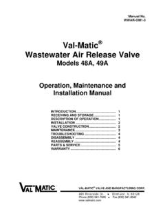
1 INSTALLATION INSTRUCTIONS . 98-1261. Brake Proportioning Valve HOW IT WORKS. Tilton Engineering 's patented, adjustable hydraulic brake proportioning valve enables the driver, Chart 1 (Screw Type). 1200. or a crew member, to adjust the brake-force to a particular wheel (or wheels). The light, rugged Maximum valve may be bulkhead or panel-mounted. The proportioning valve can also be used effectively Compression with dual master cylinder systems. 1000. The proportioning valve is often one of the less understood devices bolted onto a racecar. Outlet Pressure (PSI). 800 Midpoint of Understanding how it works from a functional standpoint will allow the driver and crew chief to Compression take advantage of its properties for a better racecar setup.
2 600. At lower pressures, the Tilton proportioning valve acts as a simple hydraulic connector. Minimum Compression The pressure going into the proportioning valve is equal to the pressure going out. There is a 1:1 400. ratio between inlet and outlet pressure. The 45 line shown in Chart 1 and Chart 2 indicates this pressure range. Once a certain pressure limit is reached, a further increase in line pressure occurs 200. at a reduced rate of 3:1 from inlet to outlet. The adjustment control alters the point at which the inlet/outlet pressure ratio changes from 1:1 200 400 600 800 1000 1200. to 3:1. For example, look at the proportioning valve Midpoint Position of Chart 1 for Screw-type Inlet Pressure (PSI). proportioning valves and Position 4 of Chart 2 for Lever-type proportioning valves .
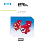
3 When the master cylinder line (inlet) pressure is above 650 PSI, the caliper line (outlet) pressure is below Chart 2 (Lever Type). the pressure in the master cylinder line. The sloping line off to the right (shown in Chart 1 & 2) 1200. demonstrates this. Below 650 PSI they are equal. Position 7. The dual-slope line gives the proportioning valve one advantage over the balance bar system. It 1000 Position 6. can be tuned for a better front-to-rear brake balance under both light and heavy braking. A par- Position 5. Outlet Pressure (PSI). ticular setting of the balance bar gives you a set front-to-rear brake balance, such as 70/30 (70% 800 Position 4. front/30% rear). Under both light and heavy braking, this balance remains the same.
4 However, the Position 3. loading on the front and rear axles does not remain the same under different braking conditions. 600 Position 2. During heavy braking, there is a large load transfer from the rear to the front axle. As the load Position 1. increases on the front axle you want a higher percentage of the braking force on the front axle. 400. The bend in the graph for the proportioning valve allows this to happen when the proportioning valve is placed in the line for the rear calipers. During heavier braking, a higher percentage of the 200. braking force is distributed to the front calipers. INSTALLATION NOTES 200 400 600 800 1000 1200. Inlet Pressure (PSI). There are a few items to remember concerning the proportioning valve: Standard Proportioning valves (P/N 90-1000 & 90-2000) At higher pressures, a piston separates the fluid at the inlet and outlet AN-3 port with 3/8"-24 threads.
5 Fittings (supplied): AN-3 male to AN-3 male sides. No fluid flows through the valve. Therefore, you cannot bleed the (P/N 73-820); AN-3 male to 3/16" inverted flare (P/N TE2089-188). system at high pressure. Use light pedal pressure, and as an extra precau- tion, move the lever to Position 7 (lever-type), or rotate adjusting knob in a Metric Proportioning Valve (P/N 90-1003 & 90-2003). clockwise direction (screw-type), to reduce internal pressure. Threads: M10 x with 74 included angle at base. No fittings supplied. The proportioning valve can be used to reduce brake line pressure, but will Lever-type portioning valves : not increase it. A typical setup has the valve oriented in such a way that when the handle is pushed towards the front of the vehicle it reduces the rear brake pres- Hooking it up backwards will not work.
6 Sure. When the handle is moved toward the rear of the vehicle it increases It can be used very effectively with a balance bar. Set the lever to Position 7. the rear brake pressure. Handle can be re-oriented by loosening the jam (lever-type) or set adjustment knob to the fully clockwise position (screw- nut and rotating the handle. To determine which direction to move the type). Adjust the balance bar until the rear brakes lock on the track with handle, refer to Chart 2 and Diagram 4. slightly less pedal effort than the front brakes. The proportioning valve Screw-type portioning valves : is connected to the rear brakes in this case. Then, adjust the valve one Rotating the adjustment knob in a clockwise direction will allow more position at a time (lever-type) or rotate the knob counter-clockwise (screw- brake pressure to be applied to the rear brakes, counter-clockwise will type) until the proper balance is achieved.
7 Reduce the pressure (when installed on the rear calipers line). The proportioning valve is ideal for cars that must retain the stock calipers and master cylinder, yet have too much rear brake when running soft tires. A prime example is SCCA A Sedan (AS). INSTALLATION . Select either the frame or bulkhead mounting style and follow the steps below: frame MOUNTING BULKHEAD MOUNTING. 1. Select a location for frame mounting the proportioning valve that allows 1. Select the location for bulkhead mounting the proportioning valve that easy access to the adjusting handle/knob. allows easy access to the adjusting handle (knob). 2. Make sure that the location allows room for the hydraulic lines and access 2. Make sure that the location allows room for the hydraulic lines and access for servicing.
8 For servicing. 3. Locate and mark the location of the mounting holes on the frame refer- 3. Locate and mark the location of the mounting hole on the frame referring ring to Diagram 4. to Diagram 1. 4. Drill two 9/32" (7mm) diameter holes in the marked locations. Debur both 4. Cut, drill or punch a 3/4" (19mm) diameter hole in the marked location. of the drilled holes. Debur the hole. 5. Test fit the valve in the prepared location and select the proper mounting 5. Refer to Diagram 1 and loosen the B-nut on the valve body and carefully hardware. Use two 1/4" (6mm) remove the handle assembly (adjusting knob) from the valve body. diameter socket head cap screws with locknuts. The length will be deter- 6. Refer to Diagram 1 and loosen and remove the jam nut.
9 Mined by your application. 7. Test fit the valve in the prepared location by sliding the valve body 6. Select the routing of the hydraulic lines carefully and avoid any heat through the hole in the bulkhead. sources such as the exhaust pipes and 8. Secure the jam nut and insert the handle assembly (adjusting knob) into manifolds. the valve body. 7. Refer to Diagram 2 and connect the outlet of the master cylinder to the 9. Rotate the handle assembly into the desired position (Lever-type). Tighten inlet of the proportioning valve. The outlet of the proportioning valve is top nut (B-Nut) with a 7/8" wrench to 20 ft-lbs before running, and verify connected to the line leading to the caliper(s). the location is suitable for ease of adjustment and servicing.
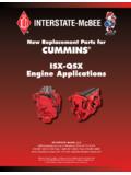
10 Make sure that the B-nut does not touch the jam nut. Otherwise, the valve handle may not be held in its proper position in the valve body. 10. Select the routing of the hydraulic lines carefully and avoid any heat sources such as the exhaust pipes and manifolds. 11. Refer to Diagram 2 and connect the outlet of the master cylinder to the inlet of the proportioning valve. The outlet of the proportioning valve is connected to the line leading to the caliper(s). OUT. IN. OUT. IN. Diagram 1 - Mounting Diagram Diagram 2 - Flow Diagram Front Rear Reduced front Reduced rear Reduced right front Reduced left, no right ". Rally Road racing Dirt front (102mm)..50" ( ). Dirt Street rods Asphalt Dirt racing OUT. Off road Trucks Used to decrease out- side Midget Stadium racing Oval Track front corner braking, which Sprint Used to compensate for fuel increases turn in and reduces Used to decrease in- side ".