Transcription of INSTALLATION INSTRUCTIONS ZAP SCREWLOK …
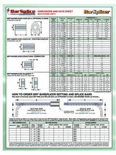
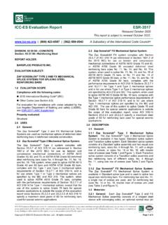
1 Page 1 of 3 Zap SCREWLOK Type 2 and epoxy Series INSTRUCTIONS 10/30/2013 INSERTION MARK 4900 Webster Street Dayton, OH 45414 Ph: (937) 275-8700 [ METRIC GRADE 420 (UNCOATED GRADE 520), CANADIAN GRADE 400] Slide the ZAP SCREWLOK coupler over one of the rebar ends until the rebar touches the positive center stop of the coupler, as shown in Figure 1. Do not under-insert, as shown in Figure 2. If the coupler is specially supplied without a center stop or if the center stop is removed, measure and mark the rebar for one half of the coupler length (L/2) before inserting it into the coupler per Figure 3 and Chart 1. Figure 1. Correct Rebar Insertion Depth Figure 2. Incorrect Rebar Insertion Depth Using an impact wrench and a socket S per Chart 1, tighten the twist-off screws starting at the end of the coupler and working your way toward the middle of the coupler. Tighten each screw until the head of the screw twists off.
2 See Chart 1 for approximate twist-off torque. THE CORRECT IMPACT WRENCH TORQUE RATING MUST BE USED WHEN INSTALLING THIS PRODUCT. For best performance and ease of INSTALLATION , Barsplice recommends the use of a inch drive pneumatic impact wrench and suitable socket. Make sure the impact wrench is rated to achieve at least the minimum impact wrench torque specified in CHART 1 to avoid stalling. The air supply line should have a minimum diameter of inch. The air compressor should be large enough to provide 100 psi (7 bar) gauge pressure & deliver 45 cfm of air flow. Figure 3. Correct Tightening Order, 1ST Side *CONTACT BPI FOR APPROPRIATE COUPLERS TO CONNECT DUAL-CERTIFIED GRADE 75/GRADE 100 LOW CARBON CHROMIUM STEEL BARS THAT CONFORM TO ASTM A1035. CONTACT BPI FOR TRANSITION SPLICES. For illustration purposes only. See CHART 1 on page 2 for numberof screws and twist-off torque. Prior to following the INSTRUCTIONS below, verify that this document is the latest version in use.
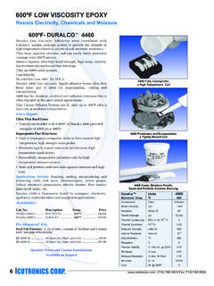
3 The latest version can be found at INSTALLATION INSTRUCTIONSZAP SCREWLOK TYPE 2 AND epoxy SERIES COUPLERSON GRADE 60 REBAR AND UNCOATED ASTM A615, GRADE 75* REBARPage 2 of 3 Zap SCREWLOK Type 2 and epoxy Series INSTRUCTIONS 10/30/2013 Once the screws on the first side have been tightened down and heads twisted off, insert the other rebar into the coupler until it butts up against the center stop per Figure 4. If the coupler has no center stop, insert the second rebar until it butts up against the first rebar. In the same order as the first side, tighten the screws until the heads twist-off working from the end of the coupler toward the middle of the coupler. Figure 4. Correct Tightening Order, 2nd Side DO NOT USE THESE COUPLERS IN CONJUNCTION WITH REBAR WHICH IS LARGER OR SMALLER THAN THE INTENDED BAR SIZE. KEEP COUPLERS CLEAN AND KEEP THREADS RUST FREE, PER FIGURE 5. STORE COUPLERS IN A CLEAN, DRY PLACE UNTIL READY TO INSTALL.
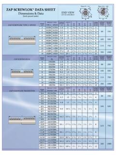
4 RUST IN THE THREADS PRIOR TO ASSEMBLY, PER FIGURE 6, IS UNACCEPTABLE BECAUSE IT COULD RESULT IN LOWER PERFORMANCE OF THE ASSEMBLED SPLICE. Figure 5. Clean Acceptable Coupler Figure 6. Unacceptable Rust in Coupler Threads CHART 1 Example of suitable impact wrench is Ingersoll Rand, IR 261 REBAR SIZE US [metric] APPROXIMATE COUPLER LENGTH L (in.) COUPLER LENGTH L / 2 (in.) NUMBER OF SCREWS PER BAR SOCKET SIZE S AVERAGE SCREW TWIST-OFF TORQUE T (ft-lb) MINIMUM IMPACT WRENCH TORQUE RATING (ft-lb) #3 [10] 5 2 2 60 250 #4 [13] 7 3 3 60 250 #5 [16] 9 4 4 60 250 #6 [19] 11 5 5 60 250 #7 [22] 13 6 5 105 500 #8 [25] 15 7 6 105 500 #9 [29] 16 8 6 215 750 #10 [32] 19 9 7 215 750 #11 [36] 21 10 8 215 750 For illustration purposes only.
5 See CHART 1 on page 2 for numberof screws and twist-off torque. Page 3 of 3 Zap SCREWLOK Type 2 and epoxy Series INSTRUCTIONS 10/30/2013 CAUTIONS AND SUGGESTIONS 1. Do not use an open-ended wrench or an adjustable wrench because of the risk of rounding-out the hexagon head prior to reaching the torque needed to twist-off the head. 2. Prior to assembly, straighten excessively bent rebar ends so that proper wedge contact is made between rebar and coupler. BAR ENDS should be straight to within inch in 18 inches. For curved rebar with a diameter that exceeds 54 feet, a bar end straightness check is not necessary. If needed, grind-off large shear lips that prevent proper insertion of rebar into coupler. DO NOT USE THIS PRODUCT ON CURVED COLUMN REBAR ENDS. 3. If removal of the center stop is necessary, use a hammer and punch or large nail to tap it out of the coupling body. 4. Replace missing screws immediately with BPI special screws only.
6 DO NOT ALLOW THREADED HOLES TO RUST. 5. If rebars are corroded, removal of rust/corrosion must be performed to the same degree as that required to bond with concrete prior to installing the Zap coupler. Testing of old or severely corroded bars is recommended to ensure the integrity of the adjoining bars and compliance to design requirements. Performance statements of Zap couplers are based upon the use of ASTM A615/A706, Grade 60 rebar or uncoated ASTM A615, Grade 75 rebar. 6. For epoxy Coated ASTM A775/A775M rebar, use the pre- epoxy coated ZAP SCREWLOK epoxy SERIES couplers supplied by Barsplice Products, Inc. Touch-up coating damage and the sheared surfaces of screws with a suitable epoxy patching kit after assembly. DO NOT APPLY FUSION-BONDED epoxy POWDER COATINGS TO UNCOATED COUPLERS or HEAT THE COUPLERS FOR THE PURPOSE OF epoxy COATING.
7 DO NOT HOT-DIP GALVANIZE UNCOATED COUPLERS. DO NOT ALLOW ABRASIVE BLAST MATERIAL TO COME INTO CONTACT WITH UNASSEMBLED THREADS. 7. In all cases, consider your own personal safety. Make sure you are securely positioned and that you will not slip or fall during INSTALLATION . Please direct all assembly questions to BarSplice Products, Inc.