Transcription of INSTALLATION / MAINTENANCE GUIDE - Master …
1 INSTALLATION / MAINTENANCEGUIDEMODEL FWT-Fanwall Technology RetrofitImproper INSTALLATION , adjustment, alteration service or maintenancecan cause property damage, injury or death. Read the INSTALLATION ,operating and MAINTENANCE instructions thoroughly before installingor servicing this YOUR SAFETY TABLE OF CONTENTSGENERAL 1 INSTALLATION CODES / 1 INSTALLATIONELECTRICAL CONNECTIONS .. 2 FANWALL ASSEMBLYFAN MOTOR CARTRIDGE 3 SECURING FAN MOTOR 4 MAINTENANCEFANWALL OPTION - FAN WHEEL/MOTOR 5 FANWALL OPTION - FAN CARTRIDGE 7 LONG TERM STORAGE (Over 1 Month).
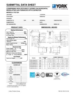
2 8 MONTHLY, YEARLY 9 START-UP INSPECTION 11 PAGE Copyright 2007, HUNTAIR, RIGHT RESERVED. NO PART OF THIS BOOK MAY BE REPRODUCED,STORED IN A RETRIEVAL SYSTEM, OR TRANSMITTED IN ANY FORM BY ANELECTRONIC, MECHANICAL, PHOTOCOPYING, RECORDING MEANS OROTHERWISE WITHOUT THE WRITTEN PERMISSION OF HUNTAIR, manufacturer reserves the right to modify the materials and specifications resulting from a continuing program ofproduct improvement or the availability of new DESCRIPTION1 INSTALLATION CODESE lectrical characteristics are shown on the unit rating unit shall be carefully installed in accordance with thestandards of the National Fire Protection Association (Na-tional Electrical Code).
3 Authorities having jurisdiction shouldbe consulted before installations are made to verify localcodes and INSTALLATION PRECAUTIONS1. The services of qualified field service personnel aremandatory for safe and proper INSTALLATION of this Air volumes and external static pressures that do notcoincide with those listed on the rating plate will ad-versely affect the performance of the unit. Pleaseconsult the factory if either of these values The following clearances from combustible materials areto be maintained: Top - 6", control side - 48", oppositecontrols - 6", bottom - 0".
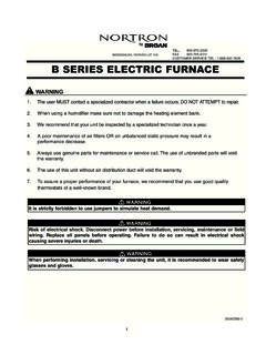
4 If roof curb is provided byothers, it must be at least 4" high and constructed fromnon-combustible This unit is designed for INSTALLATION on a level is especially true if provided with an Do not locate the supply inlet opening within 10' of anyexhaust discharge point or within 24" of any CODES / PRECAUTIONSF ollow all safety codes. Wear safety glasses and workgloves. Use quenching cloth for brazing operations. Havefire extinguisher available. Read these instructions installing or servicing system, always turn offmain power to system.
5 There may be more than onedisconnect switch. Turn off accessory heater power ifapplicable. Electrical shock can cause personal injuryor : Before proceeding, make sure all electricalservice to unit is locked in Off DESCRIPTIONH untair Fanwall Technology is a fan-array approach to airhandler design that that uses several smaller fans to replaceone larger fan, providing design flexibility, reducing mainte-nance costs, and increasing energy ConsiderationsInstalling and servicing air conditioning equipment can behazardous due to system pressure and electrical compo-nents.
6 Only trained and qualified service personnel shouldinstall or service air conditioning personnel can perform basic MAINTENANCE , suchas cleaning and replacing filters. All other operationsshould be performed by trained service personnel. Whenworking on air conditioning equipment, observe precau-tions in literature and on tags and labels attached to ConnectionsAll electrical wiring and connections including electricalgrounding must be made in accordance with the latestedition of the National Electric Code (or the edition yourauthority having jurisdiction has adopted).
7 There may alsobe local ordinances that The FWT nameplate and the drawings in Appendix Astate the line voltage and minimum ampacity require-ments for this unit. A separate line voltage power supplyshould be run directly from the building distribution panelto the electrical panel provided on the side of the FWTunit. The quantity of wires and the connection terminalsare identified on the wiring diagram in Appendix A. Allexternal wiring must be within approved conduit and havea minimum temperature rating of 90 IMPORTANT: If any of the original wire supplied with theunit must be replaced, it must be replaced with typeTHHN 90 C wire or its equivalent, except for miscella-neous 120 volt control wiring that must be type SJO90 Refer to Appendix A for other control interface ASSEMBLY3 BOLTINGFLANGESFANCARTRIDGE Fanwall AssemblyDANGER!
8 Risk of Electric ShockAlways disconnect power to the fan control panelbefore MAINTENANCE . Follow all lockout and tagout assemble fanwall, first disconnect power tothe existing fan at the main control note of all wire locations for reinstallation existing fan motor power cable from termi-nal located in motor J-Box and conduit fittingfromJ-Box as shown in the demolition existing fan/motor assembly and clean thearea sure that floor on airhandler is level and the center line of the fan cabinet air inlet openingand mark it on the air handler floor to help align thefirst fan the first fan cartridge frame needed at the centerbottom for the fanwall (inlet side).
9 See drawings for fanarray. Align the next fan cartridge needed on either sideof the first cartridge and bolt together using the boltingflanges and supplied bolts, washers, and lock the base fan cartridges are aligned properly andbolted together, use tek screws and washers to securethe bases to the floor. To further secure the bases to thefloor, mount the blank-offs for the floor with tek the next row of fan cartridges in to place and bolttogether at the bolting flanges, both side-to-side and top-to-bottom. Follow the same procedure until the entirefanwall is secure the fanwall to the cabinet, secure blank offpanels to the fan cartridge frame and the air handlercabinet using tek screws.
10 Apply caulking to blank-offpanels and fan cartridges where BOLTSBOLTING FLANGESBLANK-OFFSINLET SIDE VIEWBOLTINGFLANGESFANWALL ASSEMBLY4 Fanwall Electrical InstallationDANGER! Risk of Electric ShockAlways disconnect power to the fan control panelbefore MAINTENANCE . Follow all lockout and tagout Verify fanwall is in Layout conduit run from fan(s) to enclosureor j-box. See INSTALLATION design Attach FMC ( flexible metal conduit ) to motor j-box( Pecker head ), one J-box per Size wire ( per NEC code ) and pull from motor(s) Wire internal motor Crimp on ring terminals.