Transcription of Installation Manual
1 NOTE:Read the entire instruction Manual before starting the symbol indicates a change since the last TO DRAWING ..4 CODES AND STANDARDS ..6 ELECTROSTATIC DISCHARGE (ESD) .. Applications ..9 Downflow Left (Supply-Air Discharge) Right (Supply-Air Discharge) .. Location Relative to Cooling with Respect to Combustion and Circulating Air Locations ..18 AIR FOR COMBUSTION AND Legs (If Desired)..22 Installation In Upflow or Downflow Applications ..22 Installation In Horizontal Ducts ..23 General ..23 Ductwork Acoustical Air an ENERGY STAR Partner, PayneHeating and Cooling has determined thatthis product meets the ENERGY STAR guidelines for energy ManualPG9 MABS eries A4-WAY MULTIPOISEFIXED-CAPACITY DUAL-VENTCONDENSING GAS FURNACESIZES 040 THRU 140 Catalog No.
2 IM-PG9 MAB-01 Cancels: IM-PG9M-10 Printed in Air Arrangement ..26 Bottom Closure Connections ..28115-v ..31 Wiring of Existing Furnaces from Common Vent Systems ..33 Combustion Air and Vent Pipe Systems ..33 Condensate .. Drain , ADJUSTMENTS AND SAFETY ..48 Prime Condensate Trap With Gas of Mode ..49 Cooling Blower Mode ..50 Heat Pump Gas Input Rate ..51 Set Temperature Rise ..58 Blower Off Delay (Heat Mode)..59 Set Thermostat Heat Anticipator ..59 Check Safety Primary Limit Pressure ..61 SAFETY CONSIDERATIONSCAUTION:FURNACE RELIABILITY HAZARDI mproper Installation or misapplication of furnace may require excessive servicing or cause premature component of this furnace should be indoors with special attention given to vent sizing and material, gas input rate, air temperaturerise, unit leveling, and unit.
3 FIRE, EXPLOSION, ELECTRICAL SHOCK AND CARBON MONOXIDE POISONING HAZARDF ailure to follow this warning could result in electrical shock, fire, personal injury, or Installation , adjustment, alteration, service, maintenance, or use can cause carbon monoxide poisoning, explosion, fire,electrical shock, or other conditions which may cause personal injury or property damage. Consult a qualified installer, service agency,local gas supplier, or your distributor or branch for information or assistance. The qualified installer or agency must use onlyfactory-authorized and listed kits or accessories when modifying this and servicing heating equipment can be hazardous due to gas and electrical trained and qualified personnel shouldinstall, repair, or service heating equipment.
4 Untrained personnel can perform basic maintenance functions such as cleaning and replacing airfilters. All other operations must be performed by trained service personnel. When working on heating equipment, observe precautions in literature,on tags, and on labels attached to or shipped with unit and other safety precautions that may apply. 2 These instructions cover the minimum requirements and conform to existing national standards and safety codes. In some instances, theseinstructions exceed certain local codes and ordinances, especially those that may not have kept up with changing residential construction require these instructions as a minimum for a safe safety glasses and work gloves.
5 Have a fire extinguisher available during start-up and adjustment procedures and service :CUT HAZARDF ailure to follow this caution may result in personal metal parts may have sharp edges or burrs. Use care and wear appropriate protective clothing and gloves when handling safety information. This is the safety-alert symbol. When you see this symbol on the unit and in instructions or manuals, be alertto the potential for personal these signal words DANGER, WARNING, and CAUTION. These words are used with the safety-alert symbol. DANGER identifiesthe most serious hazards whichwillresult in severe personal injury or death.
6 WARNING signifies hazards whichcouldresult in personal injuryor death. CAUTION is used to identify unsafe practices whichmayresult in minor personal injury or product and property damage. NOTE is usedto highlight suggestions whichwillresult in enhanced Installation , reliability, or PG9 MAB Multipoise Condensing Gas-Fired Furnaces are CSA (formerly AGA and CGA) design-certified for natural and propane gases (seefurnace rating plate) and for Installation in alcoves, attics, basements, closets, utility rooms, crawlspaces, and garages. The furnace isfactory-shipped for use with natural gas. A CSA listed gas conversion kit is required to convert furnace for use with propane Fig.
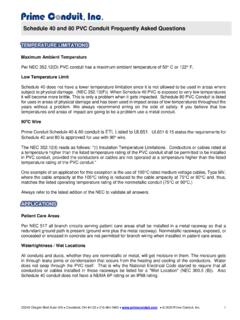
7 1 for required clearances to 1 Clearances to CombustiblesA04110 This forced air furnace is equipped for use with natural gas at altitudes 0 - 10,000 ft (0 - 3,050m), except 140 size furnaces are only approved for altitudes 0 - 7,000 ft.(0 - 2,135m).An accessory kit, supplied by the manufacturer, shall be used to convert to propane gas use or may be required for some natural gas furnace is for indoor Installation in a building constructed on site. This furnace may be installed in a manufactured (mobile) home when stated on rating plate andusing factory authorized furnace may be installed on combustible flooring in alcove or closet at Minimum Inches Clearance To Combustible Construction as described furnace requires a special venting system.
8 Refer to the Installation instructions for parts list and method of Installation . This furnace is for use with schedule -40 PVC,PVC-DWV, cpvc , or ABS-DWV pipe, and must not be vented in common with other gas-fired appliances. Construction through which vent/air intake pipes may beinstalled is maximum 24 inches (600 mm), minimum 3/4 inches (19 mm) thickness (including roofing materials).MINIMUM INCHES CLEARANCE TO COMBUSTIBLE CONSTRUCTION*Minimum front clearance for service 24 inches (610mm).140 size furnaces require 1 inch back clearance to combustible Installation on combustible floors only when installed on special base No.
9 KGASB0201 ALL,Coil Assembly, Part No. CD5 or CK5, or Coil Casing, Part No. contact is permissible only between lines formed by intersections of top and two sides offurnace jacket, and building joists, studs, or shown is for air inlet and air outlet and 140 size furnaces require 1 inch bottom clearance to combustible materials. Clearance in inchesD gagement (po).Vent clearance to combustibles 0".0 (po) D gagement d vent avec gagement avant minimum de 610mm (24 po) pour l les fournaises de 140 taille, 1 po (25mm) d gagement des mat riaux combustibles estrequis furnace is approved for UPFLOW, DOWNFLOW andHORIZONTAL fournaise est approuv e pour l Installation HORIZONTALEet la circulation d air VERS LE HAUT et VERS LE BAS.
10 *BOTTOMDESSOUS0" 3"0" 0"TOP/PLENUMDESSUS/CHAMBRE D AIR1"0" 24 MINALL POSITIONS:DOWNFLOW POSITIONS:IHORIZONTAL POSITIONS::SIDECOTESFRONTAVANTBCKARRIEAE RSERVIECL NTRTENEIVANATFRONTSIDECOTESFOUUFRNACSEEI ARNLes fl ches de d gagement ne change pas avec l orientation de la g n rateur d air arrowsdo not change withfurnace orientation. UPFLOW ORDOWNFLOWFRONTFRONTLEVEL (0") TO1/2" MAX Installation POUR LA POSITION HORIZONTALE:POUR LA POSITION COURANT DESCENDANT:POUR TOUS LES POSITIONS:U * For upflow and downflow applications, furnace must be installed level, or pitched within 1/2" of level. For ahorizontal application, the furnace must be pitched minimum 1/4" to maximum of 1/2" forward for properdrainage.