Transcription of Installation Manual - Thermapan Structural …
1 The better way to buildTMInstallation ManualFLOOR SIPs2 Floor SIP - Installation ManualSeptember 2015 FLOOR SIPsInstallation ManualTable of Contents TopicsGeneral Requirements .. 3 Materials .. 3 Protection from Dampness .. 3 Interior Finish .. 3 Electrical Wiring .. 4 Plumbing .. 4 Materials Estimation .. 5 DetailsAir Barrier Details for Air Barrier Sealants .. AB-1 Air Barrier Details for Sealing SIP Connections .. AB-2 Drawing FL-1: Floor Panel Details ..FL-1 Drawing FL-2: Floor Panel Connections (to Foundation or Existing Walls) ..FL-2 Drawing FL-3: Floor Panel Connections (to SIP Exterior and SIP Foundation Walls) ..FL-33 Floor SIP - Installation ManualSeptember 2015 FLOOR SIPsInstallation Manual1.
2 General Requirements ScopeThe basic design and construction requirements for the Thermapan Structural Insulated Panel (SIP) fl oor systems are set forth in this specifi cation. Criteria for materials, environmental control, design loads, and Structural design are included. Where requirements are based on internationally recognized standards and specifi cations, these standards and specifi cations are referenced without shall reference engineering design package for fastening arrangements. 2. Materials Floor SIP (See Detail FL-1) The Thermapan SIP is composed of an expanded polystyrene (EPS) foam core laminated between two layers of oriented strand board (OSB) with a Structural Framing Lumber shall be DOC PS 20 or NLGA or better.
3 Wire nails, ring nails, spikes and staples shall conform to CSA B111 or ANSI Wood screws shall conform to ANSI/ASME SIP screws shall conform to Caulking Compounds shall conform to CAN/CGSB or ASTM C Polyethylene Sheeting shall conform to , , or ASTM D Low expansion foam seal shall conform to AAMA Structural adhesive shall conform to CAN/CGSB 71GP26, APA AFG-01 or ASTM Decay and The minimum vertical clearance between Structural wood elements Termite Protection and the fi nished ground level is not to be less than 150 mm (6 ). In localities where termites are known to occur, clearance between the exposed exterior osb skin of the fl oor SIP and the fi nished ground level directly below shall be not less than 450 mm (18 ).
4 4 Floor SIP - Installation ManualSeptember 20154. Interior Finish A plywood underlay may be required for hardwood and ceramic tile fi Electrical Wiring It is recommended to fasten wiring to the exterior OSB layer and drill access through to interior layer. Exposed wire shall conform to local building code. 6. Plumbing Vertical plumbing penetrations 6 in diameter or less can be cut out of the fl oor SIP - Installation ManualSeptember 2015 MATERIALS ESTIMATINGF loors Estimation Only Lumber Requirements: Single lumber edging for ledger Double lumber edging under wallCaulking and Sealant Requirements: Every 1200 sqft (111 m2) of SIP equals 1 case of Expandable Foam Every 2000 sqft (185 m2) of SIP requires 1 case of SealantFasteners.
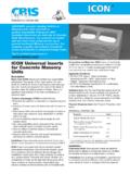
5 Recommend 2 (50mm) Ring nail or 2 (50mm) screws for connection to panel ~ times the square footage of nailing of spline SIP screws use 40% of Floor square footage AIR BARRIER DETAILSFOR AIR BARRIER 20101 TITLEREVISIONSCALEDATEREFERENCEDWG. (9255) sealants, FOAM (A) or CAULKING (B), should be applied onto the SIP in a continuous rectangular pattern along the outer most edge of the area to be BARRIERRECOMMENDED DETAILS FOR AIR BARRIER SEALANTS(A) A low expansion EXPANDABLE FOAM SEALANT should conform to the AAMA 812-04 standard. Apply a 1/2 inch or a mm diameter of a continuous bead of expandable foam sealant onto the SIP:(B) A CAULKING SEALANT should conform to ASTM C920-02 and/or CAN/CGSB Apply a 3/8 inch or a 10 mm diameter continuous bead of caulking onto the lumber spline:Expandable Foam SealantBeadEPSC aulkingBeadLUMBER STUD ORSPLINECAULKING(CONTINUOUS BEAD)AIR BARRIER DETAILSFOR SEALING SIP 2009 TITLEREVISIONSCALEDATEREFERENCEDWG.
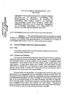
6 (9255) BARRIER RECOMMENDED DETAILS FOR SEALING SIP CONNECTIONS(3) Wood to Wood: Use caulking and a low expansion foam sealant.(2) Foam to Wood: Use a low expansion foam (SEE WOODTO WOOD)EXPANDABLEFOAMSEALANTPLATES SECTIONLUMBER SPLINESEXPANDABLEFOAMSEALANTLUMBER SPLINE,END STUD ORJOISTTOP PLATECAPBOTTOM PLATESEE VAPOUR BARRIERDETAIL (VB-1)CAULKING(SEE AB-1)CAULKING(SEE AB-1)LUMBER SPLINE(1) Foam to Foam: Use a low expansion foam SPLINE JOINTBUTT JOINTEXPANDABLEFOAM SEALANTCORNER DETAIL PLANEXPANDABLEFOAM SEALANTEXPANDABLEFOAM SEALANTEXPANDABLEFOAM SEALANTSEE VAPOURBARRIER DETAIL (VB-1)1/4 (6 mm) GAPEXPANDABLEFOAM SEALANTLUMBEREDGINGFLOOR SECTION A SECTIONPANEL FLOOR PLANFEBRUARY PANEL DETAILSFLOOR SECTION C FL-1 LUMBER EDGING UNDER WALLTHERMAPANFLOOR PANELOPTIONAL POLYETHYLENE STRIP TO PREVENT FLOOR SQUEAKFLOOR SECTION B DOUBLE WOOD SPLINETHERMAPAN FLOOR PANELEXPANDABLE FOAMSEALANTTHERMAPANFLOOR PANELTHERMAPANFLOOR PANELNOTE: REFER TO AIR BARRIER DETAILS (AB-1 & AB-2).
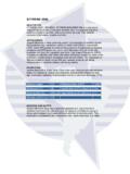
7 NOTE 2: REFERENCE FLOOR PANEL FASTENING TABLE ON CONNECTION DESIGN (CD) SHEET OF ENGINEERING DRAWINGSTAC KBLOCK FULLYUNDER POINT LOADPOSTSEE NOTE 2 FLOOR PANELCONNECTIONS(TO FOUNDATION OR EXISTING WALLS) 20112 TITLEDWG. FLOOR TO EXISTING WALLWALLEXISTINGDETAIL F3 SCREWSIPNEW FLOOR TO EXISTING WALLDETAIL F4 EXISTINGWALLSCREWSIPDETAIL F1 THERMAPANFLOOR PANELEXTERIOR WALLNEW FOUNDATIONWALL (MASONRY OR CONCRETE)VENTED AIR SPACESIP SCREWFOUNDATION WALL DETAIL F2 PIER 2X_ BEAM AS PER LOCAL BUILDING CODE 3 MIN. BEARING PIER TYPE FOUNDATION4 PANELSIP SCREW THERMAPANFLOOR PANELTHERMAPANFLOOR PANEL1-877-443-WALL (9255) : REFERENCE FLOOR PANEL FASTENING TABLE ON CONNECTION DESIGN (CD) SHEET OF ENGINEERING DRAWINGSFLOOR PANELCONNECTIONS(TO SIP EXTERIOR AND SIP FOUNDATION WALLS) 20151 TITLEDWG.
8 SIP FLOOR TO SIP WALLDETAIL F5 Thermapan WALL PANELSIP SCREWSREFER TO ENGINEERINGDRAWINGS FOR LENGTH AND SPACINGCONTINUOUS LEDGER(2X6 MINIMUM)THERMAPANFLOOR PANEL1-877-443-WALL (9255) : REFERENCE FLOOR PANEL FASTENING TABLE ON CONNECTION DESIGN (CD) SHEET OF ENGINEERING DRAWINGSSIP FLOOR PANELSCREWSFRAMED WALLOR Thermapan WALL PANEL 1-1/8 CAP PLATE 2x__ TOP PLATE 7/16 OSB SHIMSIP SCREWSCREW LEDGER INTO TOP PLATESIP FLOOR ON SIP WALLDETAIL F6 SIP FLOOR ATTACHEDTO SIDE OF SIP WALLDETAIL F7 SIP FLOOR PANELFRAMED WALLOR Thermapan WALL PANEL 1-1/8 CAP PLATE 2x__ TOP PLATE SIP SCREWTHERMAPANFLOOR PANELTHERMAPAN WALL PANELTHERMAPAN WALL PANELOPTIONAL LEDGERBELOW SIP FLOORNAILSOPTIONAL LEDGERBELOW SIP FLOOR