Transcription of Installation, Operating & Maintenance
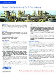
1 Kfar Hanassi, Upper Galilee 12305 Fax: 972-4-6914902 Tel: 972-4-6914911 Page 1 installation , Operating & MaintenanceCOMPACT 4 Piston Pneumatic ActuatorSizes Included:C15, C20, C25, C30, C30M, C35,C35M,C45, C45M,C60,C60M, C75, C75 MGENERALThis installation , Operation & Maintenance manual covers the instructions required for safe use of the Compact pneumatic actuator. Read the entire IOM before using this product. WARNINGS & SAFETY INSTRUCTIONSThe user of this product must know and follow all applicable these types of actuators. Improper use of the product may result in injuries or property damage. Refer to the Habonim Compact catalogue for additional product safety information or contact Habonim. 1. Assure that the actuator is isolated from the air supply or electrical ancillaries before attempting to perform any Before disconnecting the actuator from a valve, always be sure the line has been depressurized and drained.
2 Cycle the valve a few times to relieve any pressure that could be trapped in the body cavity. 3. Utmost caution must be taken when handling the actuator. have read these instructions should disassemble or assemble the Before Operating an actuator which is connected to a valve in the pipeline make sure you know the valve Do not attempt to remove the actuator pistons by use of air pressure when the covers have been Do not leave any grip key or shaft connection attached to the actuator, or try to manually operate the actuator while it is still connected to the air pressure. 7. Use the actuator within the pressure and temperature product catalogue and The operator must follow and observe any national or local safety laws and regulations. 9. Any product warranty will be invalidated in the case of improper operation resulting from misapplication or faulty Habonim bears no responsibility for external accessories attached to the Compact actuator.
3 ISSUE H-03/14 Page 2 installation , Operating & Maintenance instructionsSTORAGEThe Compact actuator has been packaged to provide protection during shipment, however, it can be damaged in transport. Prior to storage, inspect the actuator for shipping damage. Keep the actuators in their original packing box during storage. It is recommended to keep the actuators in a clean and dry environment until ready for use. The actuator has two air ports, which should be plugged during storage to prevent liquids or other materials from entering the actuator during storage. If the actuators are to be stored for a long period of time before installation , it is recommended to cycle them periodically to prevent setting of the seals. Store the actuators indoors to protect them from humidity and CONDITIONSL ubricantsThe actuators come lubricated from the factory and under normal Operating conditions do not require re-lubrication. In the event of actuator Maintenance it is recommended to use the following lubricants:For NBR O-rings use lubricant is suitable for use from -20 C (-4 F) to +80 C (+176 F) !
4 "#$%'For Viton O-rings use Molykote 111 or OKS 1110 or Phalanx EP1. * * /#;< =;>% !?"#;< (+302 F).For EPDM O-rings use only Silicone grease ( Molykote 111 or OKS 110).The lubricants are suitable for use from -40 C (-40 F) to +140 C (+284 F). For LT O-rings use KLT-2 The lubricant is suitable for use from -60 C to +140 CExplosive EnvironmentThe Compact can be installed in any appropriate potentially J Q W ' < X ? X to the ATEX Directive 94/9/EC (Equipment intended for use in Potentially Explosive Atmospheres).Special condition for safe When connected to an air actuator the maximum rubbing speed of any component within the valve must not exceed 1 m/s2. The ambient temperature range for which the equipment is suitable is dependent on the material it s constructed from the pressure at which they are to be used. Maximum withstand pressure is included within the Pressure Equipment Directive (PED) marking. Each piece of equipment has a lower ambient temperature value than is stated within the documentation provided with each individual Layers of dust shall not be permitted to build up on the actuator.
5 \ X temperature (LIT) or cloud ignition temperature (CIT) of the dust atmosphere in which the equipment is to be used with X "#$ 'X' ] ^< ^=##;<_ J `"#;<%'4. Actuators that may be located in Zone 0 or Zone 20 potentially explosive atmospheres must be installed such that they are protected from risk of impact. Actuators shall be subject to routine inspection and replaced or repaired should any damage to the surface coating be noted."' \ * | from a source known to be non-hazardous and free from ingress of foreign objects or User shall ensure any lubrication medium used has an X X "#$ * Q maximum surface temperature of installed equipment and be resistant to Supply} X ~ ' " ` ? =' inert gases may be used such as nitrogen, argon and natural gas. Thin hydraulic oil can also be used. Do not use water as a supply medium. Oxygen or hydrogen must NOT BE USED. X * W 30 microns or less. Always consult with a representative of Compact for suitability and recommended practice.
6 \ X * according to recommended instrumentation piping to connection make sure all lines have no loops and are free of water, oil or other contaminants that may be trapped in ' \ * X 'Where sealants have been used for threaded connections, care must be taken to avoid excess material being forced into the actuator PressureThe supply pressure for the Compact actuators are as follows:Double-acting: 2-8 barg (30-120 psig). Spring-return: 3-8 barg (40-120 psig). Spring-return actuators can also operate with air pressure of 2 * X `# X% * X X X shown in the Compact catalogue. When sizing an actuator to the available air supply, make sure you have adequate power in the actuator to allow the valve to complete its operation and leave enough power for safety standard temperature limits for the Compact actuators are -20 C (-4 F) to +80 C (+176 F). For temperatures below * Q X required such as grease, O-rings, pinion bearings and Compact maximum working temperature is 130 C (266 F) when used with Viton O-rings and HT Compact minimum working temperature is -60 C (-76 F) when being used with LT O-rings and LT grease.
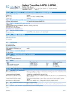
7 ABABABBAPage 3 installation , Operating & Maintenance instructionsAIR CONNECTIONSThe actuator air connections are marked A and B connects via a series of holes to all the four pistons. The air passes into the Namur cover (or insert) and through holes which are connected to the two neighboring pistons. Q ensures a quick response. W <?" <=" <=" port A is to the right and port B to the entering port A into the center chamber pushes the pistons outward and rotates the pinion CWPressure entering port B into the outer chambers pushes the pistons inward and rotates the pinion CWDouble Acting (DA)Pressure entering Port A to open:Center chamber pressurized. Pistons move outward and the pinion rotates counter clockwise (CCW).Pressure entering Port B to close:Outside chambers pressurized. Pistons move inward and the pinion rotates clockwise (CW).Spring Return (SR)Pressure entering Port A to open:Center chamber pressurized. Pistons move outward and the pinion rotates counter clockwise (CCW).
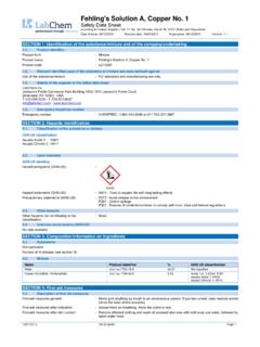
8 Springs are exiting Port A to close:Air released from center chamber. Springs drive pistons rotates clockwise (CW)When used in sub-zero temperatures it is essential to use an air dryer on the air supply line to prevent moisture. Always consult with a representative of Compact for suitability and recommended CorrosionIn corrosive environments or in high humidity environments it is recommended to use a Breather Block to avoid contaminated air from the environment entering the actuator. (See Bulletin B370 Namur Breather Block).ReducersHabonim recommends using reducers to properly control the opening / closing speed of Compact actuators, especially if Q Q ~ 'PRINCIPLE OF OPERATIONThe Compact actuator is a pneumatic quarter-turn rack & pinion actuator. Air pressure applied to the piston surface area generates thrust which transforms linear motion to rotary motion of the pinion. The Compact has four pistons centrally located around one pinion. This means that the actuator can generate twice the torque of dual piston actuators, is lightweight, occupies minimum space and has minimal air sizes C60/C60M and < " < " are vertical where port A is above port BXXXXX XX XXINDUSTRIAL VALVES & ACTUATORS LTDKFAR HANASSI, 1230500, ILCOMP CTSERIESMODELMAX PRESSURE: 120 PSI, 8 BAR0 90 +5 -5 95 85 TWO WAYT - PORTL - PORT70 20 19131913 Page 4 installation , Operating & Maintenance instructionsNAMUR Solenoid MountingConnection of the air supply is accomplished by mounting a solenoid directly onto the Namur cover which has a mounting pad conforming to the Namur standards.
9 (Only Solenoids made to the NAMUR standard can be mounted in this way.) < * J * tubing from remote solenoid 5211 or DIN 3337 * X "/?? DIN 3337) international standards and incorporates a star shaped Q J * Q Q Q ' valve can be attached by a bracket or mounted directly onto the actuator using one of the various ISO hole ADJUSTMENTThe actuator comes factory adjusted to produce a 90 rotation. The rotation is restricted by the stop (13) and four adjustment ? % Q X X | 'The screws are threaded into the actuator body and are diametrically opposed to create simultaneous and equal forces on opposite sides of the stop to eliminate off-center forces. The standard stop screws ! "; the travel limits. Other Intermediate positions can be achieved with a longer set of stop screws which will enable travel from 0 to 20 and from 90 to 70 & PUCKAll actuators are assembled with a highly visible indicator or puck. | Q X * direction arrows to identify valve position.
10 The arrows can be arranged to provide any pattern according to the valve a screw driver or sharp instrument at the arrow head to push it out and reposition as puck has three contact screws to allow signaling of any position. The puck is screwed to the pinion Namur thread.(The indicator snaps to the pinion with its Namur interface projecting above it and enabling any ancillary to connect to the pinion).The indicator assembles on the pinion with its Namur interface projecting above the pinion enabling the connection of ancillary devices to the actuators are supplied with a nameplate located on the side of the body. The information includes actuator size, model, type, spring set, threads, indicator, additional options, date of manufacture, protection rating, pressure limits and company descriptionCompact C seriesWork InstructionWeek ofmanufactureYear ofmanufactureH2H1911 Page 5 installation , Operating & Maintenance instructions123 DISASSEMBLYG eneralBefore any disassembly, make sure you read all the warnings ' Do not attempt to disassemble the actuator while it is still connected to the valve or to any ancillary device.