Transcription of Installation Operation and Maintenance Manual - …
1 Document 481200. VGD-100. Vari-Green Drive Installation , Operation and Maintenance Manual Please read and save these instructions for future reference. Read carefully before attempting to assemble, install, operate or maintain the product described. Protect yourself and others by observing all safety information. Failure to comply with these instructions will result in voiding of the product warranty and may result in personal injury and/or property damage. General Information The Vari-Green Drive (VGD) is a factory mounted WARNING. and wired variable frequency drive. It is compatible with induction and permanent magnet motors. Do not remove VGD cover for wiring or periodic It is programmed at the factory to match the inspections while power is applied or the unit is in characteristics of the fan and motor on which it is Operation .
2 Otherwise, electric shock could occur installed. from the exposed terminals and bus bars. Wait at least 1 minute after disconnecting the input power and also verify all LEDs including the Power and Charge LEDs are off before performing Safety Instructions any wiring tasks and/or periodic inspections on the VGD. As with all electrical products, read the Manual Operate VGD and control devices with dry hands. thoroughly before operating. Only qualified personnel Otherwise, electric shock could occur. should perform Maintenance and Installation . Do not Do not use VGD if power or motor cable is disassemble or repair unit. Death or injury due to damaged. electrical shock may result. To prevent injury and property damage, follow CAUTION. instructions during Installation and Operation of the Disconnect the input power if VGD has been VGD.
3 Damaged. Otherwise, fire and secondary damage Incorrect Operation of the VGD due to ignoring these or accidents could occur. instructions may cause harm and damage. Do not touch VGD immediately after shutting down or disconnecting it. It can remain hot for a few minutes. Otherwise, bodily injuries such as skin-burn or damage could occur. Do not apply power to a damaged VGD or to VGD. This Manual should be placed in a location with missing parts. where it can be accessed by the users of this product and by those that are responsible for its Do not allow lint, paper, wood chips, dust, Maintenance . metallic chips or other foreign material into the drive. Otherwise, fire or accident could occur.. Vari-Green Drive 1. Table of Contents Features General Information.. 1 Model 100. Features.. 2 Speed control options: Physical Overview.
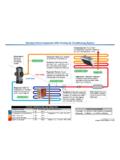
4 2. On-Board Dial Startup Procedure.. 3. 0-10 VDC signal Programming.. 4. First Application of Power.. 4 4-20mA signal Operation Notes .. 4 Other Vari-Green Controls Troubleshooting.. 5-6 Power, Run, Fault LEDs Maintenance .. 6 24 VDC @ damper actuator power output Precautions.. 6. 24 VDC @ 50mA control power output for Vari-Green Periodic Inspection.. 6 Controls Specifications.. 6. Motor Protection Thermal Overload, Over Voltage, Under Voltage, Input Phase Loss, Over Current, Overheat, Short Circuit, Hardware Error, Cooling Fan Failure R3 Filtering . Helps meet IEEE 519 without an external line reactor or filter. VGD Physical Overview Diagram EMI Jumper (J4). R. S. Control Wiring 1 2. ON. Terminal Block T. A+. A- Power Input 24. AI. U. SG. V. W. Analog Dip Switch Motor Output 2 Vari-Green Drive . Startup Procedure Power Wiring Control Wiring The Vari-Green Drive power input and output There are five terminals on the control board for connections are pre-wired at the factory.
5 Refer to connecting input signals and powering/signaling local electrical codes for branch circuit protection and a damper. proper wiring size and type. Terminal EMI Jumper (J4): The Vari-Green Drive comes from Purpose Label the factory with a jumper installed that connects +24 VDC Power, Max. On when VGD is the EMI filter to earth ground. This jumper must be A+ commanding motor to run. Useful for powering removed if the Vari-Green Drive is installed on a appropriate damper actuator. A- -24 VDC Power. Ground for A+ terminal. corner grounded power system. +24 VDC power, 50mA Max. Used to power 24. Note: For Part Number 385817, 385818 Vari-Green controls. On when VGD is powered. The VGD requires class J or K fuses size 20A or AI. Analog input signal smaller to provide short circuit protection on the (configurable via ANALOG dip switches).
6 SG Signal Ground for analog input input. If a fused disconnect was not supplied by Greenheck, fuses must be provided by others. For Part Number 386168, 386169, 386221, 386222, the VGD has internal fuse protection and does not require a fused disconnect. Speed Control Wiring Connections Analog Dip Switch Notes Option VGD Ex. Device Settings 24 RED ON 1 2. 1: ON. On-board Dial On-Board Dial AI WHITE. Part Number 384588. 2: OFF. OFF. SG BLACK. 24 __ ON 1 2. 1: OFF. 0-10 VDC Signal AI 0-10 VDC 2-10V Active Range 2: OFF. OFF. SG GROUND. 24 __ ON 1 2. 1: ON. 4-20mA Signal AI 4-20mA 4-20mA Active Range 2: ON. OFF. SG GROUND. 24 24V POWER ON 1 2. 1: OFF. Refer to control Manual Other Vari-Green 0-10V. AI wiring diagram for controls SIGNAL. connections to control 2: OFF. COMMON/ OFF. SG. GROUND.. Vari-Green Drive 3. Motorized Backdraft Damper Operation Notes Connect 24 VDC motorized backdraft damper to LED Status the A+ and A- terminals.
7 Make sure amp draw of There are three LEDs on the front cover. actuator does not exceed - Power The power LED is green when power is The VGD will energize the damper actuator when applied to the VGD. given a Run command. - Run The run LED is solid green when the VGD. After the VGD is commanded to run, there will be is running the motor and drawing current. a time delay to let the damper open before the motor starts accelerating. The run LED will be flashing green if a run command is present but the drive does not If an actuator of a different voltage or amp draw is sense motor current. used, this power source can be used to energize an interposing relay. - Fault The fault LED will flash red when a fault has occurred. See the Troubleshooting section for fault details. Programming On-Board Dial No field programming or configuration is possible with Rotate the dial clockwise to increase fan speed the VGD 100 model.
8 All motor and fan information has and counterclockwise to decrease fan speed. been set at the factory and is not adjustable. Rotating the dial full counterclockwise will cause EXAMPLE OF PARAMETERS THAT HAVE BEEN the fan to stop. FACTORY SET: 0-10V input Motor Voltage The fan will operate from 2-10 VDC. 2V is Motor Speed minimum speed and 10V is maximum speed. the fan will be off. Motor FLA. 4-20mA input Acceleration/Deceleration Time The fan will operate between 4-20mA. 4mA is Min/Max Frequency minimum speed and 20mA is maximum speed. Note: If the motor is changed to a motor with a From 0-4mA the fan will be off. different voltage, speed or FLA the VGD must be Vari-Green Controls replaced as well. Refer to specific Vari-Green Control instruction Manual for operational details. First Application of Power Belt Drive Fans Warning: Ensure fan is properly installed and the Where the Vari-Green Drive is installed on a belt rotating parts can freely rotate.
9 Loose tools, parts drive fan, the belt/pulley sizes have been selected and clothing must be secured before starting fan. for a fan RPM that corresponds to the max RPM. Stay clear of rotating shafts, belts and pulleys. for the motor size that was ordered when the VGD. 1. Apply the proper input voltage to the VGD after all is running at max frequency. wiring connections have been made. Note: The design fan RPM may be less than the 2. Provide the drive with a run command (rotate dial maximum fan RPM. clockwise or provide a control signal greater than Warning: Replacing the belts/pulleys with a 2 VDC or 4mA). combination that increases the fan speed may 3. Check rotation of fan to ensure it matches the overload the motor/VGD and cause a fault. rotation direction label on the fan. The rotation Never exceed the maximum fan RPM.
10 Should be factory set. a. If incorrect, disconnect and lock-out power, then swap any two of the three leads between the VGD and motor Note: Swapping leads on the input of the VGD. will have no effect on rotation. 4. Slowly ramp fan to full speed and make sure no faults are present and the fan is operating smoothly. 4 Vari-Green Drive . Troubleshooting Faults When a fault is present, the VGD turns off its motor LED States output and flashes the Fault LED. Each fault is Run LED Fault LED Description associated with a certain number of blinks. The LED. will blink for second for each blink followed by OFF OFF VFD is off and there are no faults a 2 second break. The number of second blinks ON OFF VFD is running and there are no faults indicates the fault present. Blinking OFF. Run command present with no proof of flow Number Fault blink OFF VFD is off with Fault of LED LED Blink Fault Fault # Fault sequence Blinks 1 Thermal Overload 2 Motor Overcurrent 1 Overcurrent 3 Overcurrent 5 Output Phase Open 9 PM Motor Sync Fault 2 Over Voltage 6 Over Voltage 3 VGD Overheat 10 VGD Overheat 7 Under Voltage 4 Under Voltage 8 Input Phase Open 5 VGD Short Circuit 4 VGD Short Circuit 6 Cooling Fan Failure 12 Cooling Fan Failure Limit Switch Failed to 13.