Transcription of Installation, Operation and Maintenance Manual
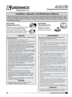
1 Universal Single Width Fans1 installation , Operation and Maintenance ManualPlease read and save these instructions for future reference. Read carefully before attempting to assemble, install, operate or maintain the product described. Protect yourself and others by observing all safety information. Failure to comply with these instructions will result in voiding of the product warranty and may result in personal injury and/or property 479870 Model USFS eries 100, 300 and 500 Universal Single Width FansSeries 500 Belt DriveSeries 300 Belt DriveSeries 100 Direct DriveSeries 100 Belt DriveSeries 500 Direct DriveNOTEFor further details on safety practices involving industrial and commercial fans, refer to AMCA Publication Single Width Fans2 Table of ContentsGeneral Safety Information 3 General Information 4-5 installation 6-7V-Belt Drives 8 Vibration
2 9 Rigging and Lifting 10 Field Coating Touch-Up Procedure 11 Radial Gap, Overlap and Wheel Alignment 12 Unit Start-Up 13-14 Variable Frequency Drive Operation 15 Routine Maintenance and Operation 16-17 Bearing Replacement 18 Parts List
3 19-22 Warranty Statement 22 Troubleshooting 23 installation / Start-up Checklist Back coverOur Commitment Back coverUniversal Single Width Fans3 General Safety InformationOnly qualified personnel should install this fan.
4 Personnel should have a clear understanding of these instructions and should be aware of general safety precautions. Improper installation can result in electric shock, possible injury due to coming in contact with moving parts, as well as other potential hazards. Other considerations may be required if seismic activity is present. If more information is needed, contact a licensed professional engineer before moving Follow all local electrical and safety codes, as well as the National Electrical Code (NEC) and the National Fire Protection Agency ( nfpa ), where applicable. Follow the Canadian Electric Code (CEC) in The rotation of the wheel is critical. It must be free to rotate without striking or rubbing any stationary Motor must be securely and adequately Do not allow the power cable to kink or come in contact with oil, grease, hot surfaces or chemicals.
5 Replace cord immediately if Verify that the power source is compatible with the Before installation , it is important to be certain the mounting surface will bear the operating weight of the unit. For proper unit Operation , it is also important that it be operated in a completely level For further details on safety practices involving industrial and commercial fans, please refer to AMCA Publication All fan motors should have disconnects located in close visual proximity to turn off electrical service. Service disconnects shall be locked-out when Maintenance is being All moving parts must have guards to protect personnel. Refer to local codes for requirements as to the number, type and design. Fully secure fan wheel before performing any Maintenance . The fan wheel may start free wheeling even if all electrical power has been disconnected.
6 Before the initial start-up or any restart, check the fan assembly to make sure that all parts are securely installed and in working order. Do not spin fan wheel faster than the maximum cataloged fan RPM. Adjustments to fan speed significantly affects motor load. If the fan RPM is changed, the motor current should be checked to make sure it is not exceeding the motor nameplate USF models may include an integrated electrical disconnect mounted and wired into the fan from the Motor Cover, Weatherhood, Shaft, Belt, Inlet or Outlet GuardDo not operate fans without proper protective devices in place. Failure to do so may result in serious bodily injury and property damage. Check local codes to ensure compliance for all protective DoorsBefore opening access doors, ensure the fan wheel has stopped moving and that the wheel has been secured from being able to rotate.
7 Do not operate fan without access door in its fully closed Pressure and SuctionIn addition to the usual hazards associated with rotating machinery, fans also create a dangerous suction at the inlet. Special caution needs to be used when moving around a fan, whether it is in Operation or not. Before start-up, make sure the inlet area is clear of personnel and loose ConnectionsBefore electrical connections are made, the supply voltage, phase and ampere capacity must be checked for compatibility with the fan motor. In addition, the supply wiring must be properly fused and conform to local and national electrical codes. If the unit is supplied with a safety disconnect switch, ensure proper wiring to the fan motor. Be sure the disconnect is switched to the OFF position before connecting supply wires.
8 If no disconnect is supplied, ensure the supply wire is not live before connection. Supply wires are then connected to the optional safety disconnect switch (if supplied) or Single Width Fans4 To ensure a successful installation , the instructions in this Manual should be read and adhered to. Failure to comply with proper installation procedures may void the and System Identification TagsEach fan has a permanently affixed manufacturer s engraved metal nameplate containing the model number and individual serial tag shown is an example of an identification nameplate on the fan. The information provides general details about the fan, as well as containing specific information unique to the unit. When contacting your local manufacturer s representative with future needs or questions, have the information on this label available.
9 Tags are mounted in an area which is clearly visible, usually on the side of the fan SeriesThe tag above depicts the factory provided tag on the outside of your unit. There are three lines labeled Model, S/N and Mark. In the Model line, the 3rd figure in the nomenclature represents your fan receiving the product, check to ensure all items are accounted for by referencing the delivery receipt or packing list. Inspect each crate or carton for shipping damage before accepting delivery. Alert the carrier of any damage detected. The customer will make a notation of damage (or shortage of items) on the delivery receipt and all copies of the bill of lading which is countersigned by the delivering carrier. If damaged, immediately contact your local representative. Any physical damage to the unit after acceptance is not the responsibility of that all required parts and the correct quantity of each item have been received.
10 If any items are missing, report shortages to your local representative to arrange for obtaining missing parts. Sometimes it is not possible that all items for the unit be shipped together due to availability of transportation and truck space. Confirmation of shipment(s) must be limited to only items on the bill of are to be rigged and moved by the lifting brackets provided or by the skid when a forklift is used. Location of brackets varies by model and size. Handle in such a manner as to keep from scratching or chipping the coating. Damaged finish may reduce the ability of the fan to resist corrosion. Fans should never be lifted by the shaft, fan housing, motor, belt guard, windband or and Maintenance During StorageWhile in storage, inspect fans once per month. Keep a record of inspection and Maintenance moisture or dirt accumulations are found on parts, the source should be located and eliminated.