Transcription of INSTALLATION OPERATION AND SERVICE MANUAL
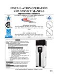
1 6226 Netherhart Road, Mississauga, Ontario, L5T 1B7 99-0212 Rev. 02 INSTALLATION OPERATION AND SERVICE MANUAL GAS FIRED WALL HUNG & FLOOR MOUNT RESIDENTIAL COMMERCIAL STAINLESS STEEL BOILERS DynaMax HS SERIES HYDRONIC HEATING Models; DMH081, 101, 151, 201, 251, 211, 261, 291, 391, 501, 601, 701, 801 HOT WATER SUPPLY Models; DMW082 ,102, 152, 202, 252, 212, 262, 292, 392, 502, 602, 702, 802 COMBINATION HEATING/HOT WATER SUPPLY Models; DMC083, 103, 153, 203, 253, 213, 263, 293, 393, 503, 603, 703, 803 H HLW WARNING: If the information in these instructions is not followed exactly, a fire or explosion may result causing property damage, personal injury or death Do not store or use gasoline or other flammable vapours and liquids in the vicinity of this or any other appliance. WHAT TO DO IF YOU SMELL GAS o Do not try to light any appliance, o Do not touch any electrical switch; do not use any phone in your building, o Immediately call your gas supplier from a neighbour s phone.
2 Follow the gas supplier s instructions, o If you cannot reach your gas supplier, call the fire department. Qualified installer, SERVICE agency or the gas supplier must perform INSTALLATION and SERVICE . To the Installer: After INSTALLATION , these instructions must be given to the end user or left on or near the appliance. To the End User: This booklet contains important information about this appliance. Retain for future reference. Contents PART 1 GENERAL INFORMATION .. 1 1 SPECIAL INSTRUCTIONS TO OWNER .. 1 CHECKING EQUIPMENT .. 1 DISPLAY UNIT .. 1 SEQUENCE OF OPERATION .. 1 Heat Transfer Process .. 1 End of 2 INSTALLATION CODES .. 2 WARRANTY .. 2 REMOVAL OF EXISTING APPLIANCE .. 3 BOILER/FURNACE ROOM OPERATING CONDITION .. 3 LOCATION OF UNIT .. 3 CLEARANCE FROM COMBUSTIBLE MATERIAL .. 4 PART 2 AIR INLET AND VENTING .. 8 GENERAL VENTING GUIDE .. 8 CATEGORY IV VENTING .. 8 Approved Venting Materials Category IV.
3 8 CATEGORY II VENTING .. 9 Approved Venting Materials Category II .. 9 COMBINED COMBUSTION AIR INLET .. 10 VENT TERMINATION AND AIR INLET CLEARANCES .. 10 Sidewall Venting .. 10 Sidewall Air Inlet .. 11 Sidewall Concentric Vent/Air .. 11 Vertical Direct Venting .. 12 PART 3 GAS CONNECTION .. 13 GAS CONNECTION .. 13 GAS PIPING .. 13 INSTALL PIPING .. 13 CHECKING GAS SUPPLY PRESSURE .. 13 HIGH and LOW GAS PRESSURE SWITCHES (Optional) .. 14 AIR/GAS RATIO VALVE .. 14 14 PART 4 WATER CONNECTION .. 15 FREEZE PROTECTION OUTDOOR INSTALLATION .. 15 WARNING REGARDING CHILLED WATER SYSTEMS .. 16 INLET AND OUTLET CONNECTIONS .. 16 MINIMUM PIPE SIZE REQUIREMENTS .. 16 HEAT EXCHANGER .. 16 LOW WATER TEMPERATURE SYSTEMS .. 16 PIPING ARRANGEMENTS .. 16 Field Supplied Components .. 16 FLOW PROVING DEVICE (wall mount models and combination models only) .. 18 WATER FLOW SWITCH (Floor mount hydronic and DHW models only).
4 18 LOW WATER CUTOFF (If Equipped) .. 18 RELIEF VALVE .. 18 DHW TUNING VALVE (combination models only) .. 18 PART 5 ELECTRICAL & CONTROLS .. 19 ELECTRICAL CONECTIONS .. 19 HIGH LIMIT .. 19 DYNAMAX HS 19 SERVICE PARTS .. 19 IGNITION MODULE LOCKOUT FUNCTIONS .. 20 ERROR TABLE .. 20 MANUAL Reset Codes .. 20 Automatic Reset Codes .. 20 PART 6 CONTROL PANEL .. 21 DYNAMAX HS 21 SETTING THE DYNAMAX HS CONTROLLER .. 21 PART 7 COMPONENTS .. 37 DIRECT SPARK IGNITER .. 37 FLAME SENSOR .. 37 COMBUSTION AIR FAN .. 37 GAS VALVE .. 37 OUTER JACKET .. 37 PART 8 TROUBLESHOOTING .. 38 SETTING THE CORRECT 47 GAS VALVE ADJUSTMENT PROCEDURE .. 47 PART 9 MAINTENANCE .. 49 EXAMINE THE VENTING SYSTEM .. 49 VISUALLY CHECK MAIN BURNER FLAMES .. 49 CLEANING BOILER HEAT EXCHANGER .. 49 CONDENSATE TREATMENT .. 50 IGNITER AND FLAME SENSOR ELECTRODES .. 50 CHECK IGNITER GROUND WIRING .. 50 BURNER MAINTENANCE.
5 51 Burner Removal and Cleaning .. 51 REMOVAL OF COMBUSTION CHAMBER LINING .. 51 COMBUSTION AND VENTILATION AIR .. 51 GAS VALVE VOLTAGE .. 52 COMBUSTIBLE MATERIALS .. 52 FREEZE PROTECTION FOR INDOOR & OUTDOOR INSTALLATIONS .. 52 FREEZE PROTECTION FOR A HEATING BOILER SYSTEM (Optional) .. 52 PART 10 INSTALLATIONS .. 53 CHECKING THE INSTALLATION .. 53 CHECKING THE CONSTRUCTION .. 53 HEATING BOILER INSTALLATIONS .. 53 INSPECT & RECHARGE CONDENSATE COLLECTION/NEUTRALIZING RESERVOIR .. 53 WATER CONNECTIONS .. 53 PIPING LENGTHS .. 53 54 DOMESTIC HOT WATER WITH STORAGE TANK .. 54 DOMESTIC HOT WATER WITH PLATE HEAT EXCHANGER .. 54 TEMPERATURE RISE AT FULL FIRING RATE .. 55 LEAD LAG SETUP .. 56 LOCAL/REMOTE SWITCH .. 57 MODBUS/LOCAL SWITCH .. 57 APPLIANCE .. 57 PART 13 PIPING DIAGRAMS .. 58 PART 14 EXPLODED VIEW & PARTS 63 PART 15 ELECTRICAL DIAGRAMS .. 72 DM 80- 299 INTERNAL WIRING 72 DM 399 800 INTERNAL WIRING DIAGRAM.
6 73 FIELD 75 System Sensor .. 75 Lead Lag Setup .. 75 1 PART 1 GENERAL INFORMATION INTRODUCTION The DynaMax HS boiler is a forced draft appliance utilizing a premix power burner based on a push through design which offers several venting options. Heat output is controlled by a one to one air/gas ratio control gas valve which provides seamless modulation. The boiler provides central heating, domestic hot water or combination heating with DHW priority at working pressure up to 160 PSI. It is designed for use with a fully pumped and pressurized water system. The boiler/water heater will automatically modulate to provide heat outputs from 100% down to approximately 20% of rated input. The DynaMax HS utilizes a negative pressure gas valve. The OPERATION of the fan will generate a negative pressure in the venturi, which draws in a matching amount of gas through the valve.
7 During OPERATION the DynaMax HS maintains steady state efficiency across the entire range of modulation. Air and gas are metered in precise proportion (1:1 Ratio) allowing combustion characteristics which determine efficiency to remain the same over the entire operating range. The DynaMax HS is designed so that all of the sensible heating value and most of the latent heat is being transferred to the water. SPECIAL INSTRUCTIONS TO OWNER This MANUAL supplies information for the INSTALLATION , OPERATION and servicing of the appliance. It is strongly recommended that this MANUAL be reviewed completely before proceeding with an INSTALLATION CAUTION It is important that all gas appliances are installed by a qualified installer/technician. It is in your own interest and that of safety to ensure that all local codes, and all the following NOTES and WARNINGS are complied with.
8 Installing, servicing or adjusting this appliance should be performed only by a qualified installer/technician that is trained by Camus Hydronics. The serviceman must utilize a combustion analyzer with CO2, CO, and draft gauge, to set the appliance according to Camus Hydronics recommendations, prior to commissioning. NOTE RETAIN THIS MANUAL FOR FUTURE REFERENCE CHECKING EQUIPMENT Check for signs of shipping damage upon receiving equipment. Pay particular attention to parts accompanying the boiler, which may show signs of being hit or otherwise being mishandled. Verify total number of pieces shown on packing slip with those actually received. In case there is damage or a shortage, immediately notify carrier. DISPLAY UNIT The display unit will indicate status and will display selected temperature. Refer to Part 6 Control Panel, which provides details to modes and error codes displayed on the appliance.
9 SEQUENCE OF OPERATION 1) Power switch is placed in the ON position. 2) Minimum 120 VAC 60Hz single phase (15A circuit) is supplied to the DynaMax HS field connection board. 3) 24 Vac power is supplied to the DynaMax HS Controller which provides all setup and ignition control functions. 4) After the appliance water pump starts, flow is proven by the flow proving device or flow switch. The normally open dry contacts in the low water cutoff (LWCO), if supplied, is to be wired in series with the normally open contacts of the flow proving device. 5) Locate the probe type LWCO in the piping at least some distance above the boiler/ inlet connection. In all cases check with local codes. 6) Depending on the selected mode, the appliance operates as a master or slave configuration. 7) The DynaMax HS controller initiates a startup sequence once it receives a heat demand. 8) The DynaMax HS controller energizes the on-board pump and starts to ramp up the voltage to the electrically commutated DC motor of the combustion fan.
10 9) The fan will run at pre-purge speed until the pre-purge timer is satisfied. Once this is complete the DynaMax HS controller provides a signal to ignition fan speed. 10) The DynaMax HS controller goes through internal safety checks and if this is satisfied the ignition sequence begins. 11) The DynaMax HS controller supplies voltage to the air/gas ratio control valve. The air/gas ratio control valve senses the pressure across the venturi and supplies gas to pre-mix with air. 12) The igniter will spark for 4 seconds, with the gas valve opened, and the fan running at ignition speed. 13) Spark igniter lights the air/gas mixture. The DynaMax HS controller looks for a minimum flame rectification signal of from the flame sensor. If the signal is present, the DynaMax HS Controller will allow the gas valve to remain open. The burner is now firing at starting input rate. 14) Boiler will modulate to the correct fan speed to meet heat demand.