Transcription of Installation Operation Maintenance ODYSSEY
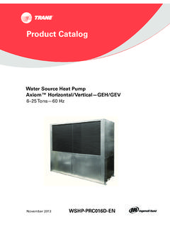
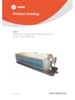
1 Installation Operation Maintenance ODYSSEY . Light Commercial split System 5-20 Tons TWE Model 50 Hz / 60 Hz Air Handling Models R22 Series R407C Series TWE 120 CD / TWE 120 C3 TWE 120 ED / TWE 120 E3. TWE 160 CD / TWE 160 C3 TWE 160 ED / TWE 160 E3. TWE 180 CD / TWE 180 C3 TWE 180 ED / TWE 180 E3. TWE 210 CD / TWE 210 C3 TWE 210 ED / TWE 210 E3. TWE 240 CD / TWE 240 C3 TWE 240 ED / TWE 240 E3. February 2013 TWE-IOM01-EN0213. Model Nomenclature Air Handling Unit Model Nomenclature TWE 120 C D 0 0 A A. TWE = Cooling Only and Heat Pump Service Digit Air Handling Unit (Convertible) A = First Parts List Minor Design Sequence A = First Design Sequence B = Second Design Sequence Nominal Gross Cooling Capacity (MBH) C = Third Design Sequence 120 = 120 MBH Factory Installed Options # 2.
2 160 = 160 MBH 0 = No Options 180 = 180 MBH For TWE model A = Discharge Plenum(Vertical application). 210 = 210 MBH B = Return Air Grille 240 = 240 MBH C = Discharge Plenum and Return Air Grille S = Special request to be defined and approved Major Design Sequence Factory Installed Options # 1. C = R22 Refrigerant 0 = No Options E = R407C Refrigerant A = 1 HP Fan Motor B = 2 HP Fan Motor C = 3 HP Fan Motor D = 5 HP Fan Motor E = HP Fan Motor Electrical Characteristics D = 380-415/3/50. 3 = 230/3/60. 2 TWE-IOM01-EN0213.
3 Contents Model Nomenclature 2. General Information 4. Unit Installation 5. General Data 10. Electrical Wiring 11. Dimensional Data 12. Operation and Start-up 17. Maintenance 18. Trouble Shooting 19. TWE-IOM01-EN0213 3. General Information Foreword All unit (both single and dual circuits), These instructions do not attempt to have one drain pan that can be cover all variations in systems, nor to installed in any one of four positions. provide for every possible contingency This allows for vertical or horizontal to be met in connection with applications and left or right exit.
4 Installation . Should further information be desired or should particular Note: Warnings and Cautions . problems arise which are not appear at appropriate places in sufficiently covered for the purchaser's this manual. Your personal purpose, the matter should be referred safety and the proper Operation to the manufacturer. of this machine require that you follow them carefully. The Reception manufacturer assumes no On arrival, inspect the unit before liability for installations or signing the delivery note.
5 Specify any servicing performed by damage on the delivery note, and send unqualified personnel. a registered letter of protest to the last carrier of the goods within 72 hours Handling of delivery. Notify the local Trane Sales The unit will be supplied with a Office at the same time. The unit shipping base and protective should be totally inspected within 15 packaging over the unit casing. The days of delivery. If any concealed packaging should be kept on the unit damage is discovered, stop unpacking during handling or storage on site.
6 The shipment. Take photos of the damage material if possible. Notify the If it is necessary to remove the carrier immediately by phone and packaging for inspection prior to registered mail. Notify the local Trane completion of on site handling, retain Sales Office. Concealed damage must packaging parts and reapply them by be reported within 15 days of delivery. tapping in position to prevent damage Check the unit nameplate to confirm to the casing. The unit as supplied has that the proper unit was shipped.
7 A shipping base which is suitable for Available power supply must be handling by a fork lift truck. If it is compatible with electrical necessary to sling the unit, use characteristics specified on spreader bars under the shipping component nameplates. base. Ensure that ropes do not cause abrasion to the surface of the unit. General Information This manual covers the Installation Operation , and Maintenance of the WARNING: Open and TWE120C single circuit air handlers, lock unit disconnect to prevent and the TWE160C, TWE180C, injury or death from electric TWE210C and TWE240C dual circuit shock or contact with moving air handlers.
8 These new air handler parts before attempting any models are completely redesigned to Installation or Maintenance . incorporate a single slab coil assembly, improved application Inspection flexibility, servicing and Maintenance Inspect material carefully for any accessibility, and an improved shipping damage. If damaged, it must accessory line. They are of the fully be reported to, and claims made convertible type (vertical to horizontal) against the transportation company. without field removal or re-orientation Replace damaged parts with of the coil assembly.
9 (For TWE model) authorized parts only. Check the unit They are shipped in the vertical nameplate to confirm that the proper position. unit was shipped. Available with electrical characteristics specified on component nameplates. 4 TWE-IOM01-EN0213. Unit Installation Table 1 - Total unit weight and corner weights (kg) Caution : Use spreader bars to prevent straps from damaging Shipping Net Corner Weights the unit. Install the bars between Model Configuration lifting straps, both underneath Maximum Maximum #1 #2 #3 #4.
10 The unit and above the unit. This TWE120 Vertical 180 154 35 39 40 37. Horizontal 180 154 84 39 39 84 will prevent the straps from TWE160 Vertical 297 275 69 69 72 70 crushing the unit cabinet or Horizontal 297 275 70 63 77 69 damaging the unit finish. TWE180 Vertical 310 285 72 72 74 72. Horizontal 310 285 73 66 80 71. TWE210 Vertical 379 355 89 89 92 90. Installation Consideration Horizontal 379 355 91 82 99 89 For proper Installation and Operation , TWE240 Vertical 385 361 91 91 94 91 check each of the following before Horizontal 385 361 92 83 101 90 mounting the units.