Transcription of Instructions For Converting A Rumble Seat to A Trunk in ...
1 1 Instructions For Converting A Rumble Seat to A Trunk in Roadsters and Coupes The Ford Way Part 1 as of May 15, 2015 by The Model A ers The following article is a spin-off of the May 2, 1928 Indianapolis Ford Service Letter titled Instructions for Installing Rumble Seat in Roadsters and Business and Standard Coupes . The only exception is that we will be going the other way, Converting a car with a Rumble seat back to a Trunk . Step 1. For easy access, remove the left and right rear fender guard assembly, and the rear spare tire carrier.
2 There were two types of spare tire carrier assemblies: The first, to the end of March 1928, had the upper bolt passing through the spare tire carrier to the underneath back side of the rear panel and was attached with a castle nut and cotter pin (In some cases, there may be a lock washer, nut, and cotter pin). The second type of assembly had the bolt and lock washer passing through the underneath back side and was screwed into the spare tire carrier assembly and remained so throughout production.
3 Step 2. Remove the right rear fender and the fender step plate, A-41563, from the top of the fender. The step plate hole in the fender will have to be filled, and the fender repainted. There were various styles of step plates throughout the Model A production years. Step 3. Remove the lower step bracket and step plate. There were two types of assemblies. With the first type the step bracket, A-41566, was attached to the rear body sill where the forward hole in the step bracket engaged the rear fender iron bolt on the inside of the sill, and the rear end was bolted to the sill at the hole in the corner plate at the end of the sill.
4 With the second type the step bracket, A-41572, was attached to the rear bumper arm assembly. 2 Step 4. Open the rear deck door and remove the seats, floor mat, and the left and right side cardboards. This will give easy access in removing the deck door and hinges. Step 5. Remove the left and right deck door hinge and arm assemblies, also called arm (deck door hinge) and base assembly, from the deck door body hinge, leaving them attached to the deck door, and remove the deck door.
5 Then remove the left and right deck door body hinges from the rear deck pillar and drain trough. Step 6. Remove the deck door hinge and arm assemblies from the deck door, the lock and handle assembly, and the deck door lock from the front end of the deck door. The hole in the deck door must be filled and the deck door repainted. An option would be to install a rubber plug, A-41540, in the hole left in the front edge of the deck door providing you can find an original as they do not reproduce this plug.
6 Step 7. Remove the wood slats from the left and right side of the compartment. Step 8. Remove the left and right upper deck door guides, A-41514, from the upper corners of the deck door opening. Remove the left and right deck door bumpers, A-41518-A, from the upper corner plates of the upper deck opening. Step 9. Remove the striker plate, A-52500, from the front of the deck door opening. (Some cars had screws in these holes where trunks were used, some did not.)
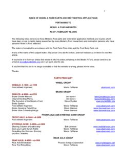
7 Step 10. Remove the rear floor pan (rear curved Inner panel) by removing the screws, nuts and lock washers at each side of floor pan from the rear deck corner plates. Remove the deck door bumper brackets, A-52486, for coupes, and A-41536, for roadsters, from the bottom of the floor pan. Remove the remaining screws, nuts and lock washers from the rear edge and the front edge in the center and remove the rear floor pan. You are now ready to assemble the items for the Trunk assembly.
8 3 THE DECK DOOR The deck door assembly, also called the deck door, was exactly the same size for 1928-29 and 1930-31. Those which were assembled for Rumble seat compartments were part # A-52435, and those for Trunk compartments were part # A-41440. If the deck door was assembled on a car which came with a Trunk , it is likely the deck door did not possess the D nuts which were required for the Rumble seat hinge brackets for a conversion from Trunk to Rumble seat.
9 However we have seen trunks on original cars with D nuts already installed and ready for the conversion. Although the 28-29 deck doors are the same size as the 30-31 deck doors, they differ from each other on the inner skin construction. The 1928-29 inner-skin construction of the deck door is recessed on both ends (Fig. 1) where the deck door handle shaft comes through the outer skin for both Trunk and Rumble seat assemblies. This requires the short extension handle and the A-41604/A-41604-A lock assembly.
10 (Fig. 1) Note to Helen: Please point, with red arrows, the recessed areas, upper and lower of the Deck Door. 4 The 1930-31 deck door inner-skin construction is stamped straight across on the upper end (Fig. 2) for a Rumble seat assembly. This requires the long extension handle and the A-41604-B lock assembly. However, on the lower edge of the 30-31 deck door, it is the same configuration as the 28-29 deck doors (Fig. 1) which was used for Trunk assemblies, thus requiring the short extension handle and the A-41604/A-41604-A lock assembly.