Transcription of INSTRUCTIONS FOR RING AND PINION SET INSTALLATION
1 IMPORTANT! INSTRUCTIONS FOR RING AND PINION SET INSTALLATIONRICHMOND GEAR HIGHLY RECOMMENDS THAT YOU READ THIS SET OF INSTRUCTIONS COMPLETELY BEFORE BEGINNING THE INSTALLATION OF THIS NEW GEAR SET. CORRECT INSTALLATION CAN BE THE DIFFERENCE BETWEEN A SAFE EXTENDED GEAR PREMATURE Remove the old gear set and thoroughly clean both the ring gear carrier and rear end housing with solvent. After cleaning, air dry all parts and inspect all components for Verify you have purchased the correct gear ratio. This can be checked by dividing ring gear tooth count by the PINION tooth count.
2 RING GEAR TOOTH COUNT 35T PINION GEAR TOOTH COUNT 10T 35 10 = :13. Many differential cases have many thousands of miles of service. Check all threads in the case for wear. It may be necessary to chase the threads with an engineering tap to clean and align the threads. When changing case bolts, check to make sure they are not too long and bottom out in the ring Check side bearing adjusters as they are often warped and out of shape, making ring and PINION settings difficult. Replace as Check the backside face of the ring gear for flat-ness. Generally, after heat treating there may be a degree of taper.
3 This may be rectified by lapping gear with sand paper on a glass flat plate. This will give you a more even and uniform pattern when set-ting up your new gear Careful attention should be given to blueprinting your differential. Accurate clearance will lead to a longer life for your unit. The same care and detail as used in engine assembly should be All new parts should be thoroughly cleaned be-fore assembly and checked for damage. PINION bear-ings should never be removed from the old PINION and refitted to the new PINION as this may void any warranties. Always install new Examine the ring gear mounting surface for nicks or burrs which might prevent a flush mounting of the newly installed ring gear.
4 Ring/ PINION tooth depth variations can result from a ring gear that is cocked on its mounting surface. If a ring gear spacer is to be used, also check it for surface imperfections. Nicks or burrs can be removed by using block-backed grit paper or a small file. Following material removal, rewash in solvent and air dry. Mount ring gear. Loc-tite ring gear bolts and torque to factory All ring gears and pinions have been LAPPED in sets and should never be mixed with another ring gear or PINION . Check to see that serial numbers are the same on the ring gear and INSTRUCTIONS Each ring and PINION is pre-run and marked on the PINION face with its proper depth setting called the Checking Distance.
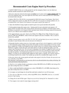
5 This dimension is from the face of the PINION to the axle center-line. A setting tool must be used to measure the checking distance. Pin-ion depth is adjusted by adding or subtracting shim distance. Stay +/- .002 of the PINION dimension (see Illustrations A and B ).11. Once PINION depth is achieved using a new crush collar or preload shim pack (Dana ), set PINION bear-ing preload to 15 inch-pounds rotating torque with used bearings, and 25 inch-pounds with new bear-ings. Once preload is set, install the seal and Loctite PINION nut. 12. Once the PINION gear is installed, position ring gear and carrier into housing to check backlash.
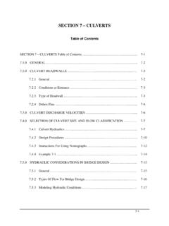
6 Each ring gear and PINION is developed to run at .007 to .009 backlash for street gear Adjustments for backlash are done by spanner rings in the housing or shim packs behind the carrier bearing cups (GM or Dana ). Always be sure carrier bearings are pre-loaded. The carrier should not fall out of the housing, but should have to be tapped in during final INSTALLATION . Replace bearing caps and torque to factory You are now ready to verify the tooth contact pattern. A gear marking compound should be used. Paint gear teeth with compound in several spots and rotate ring gear several revolutions.
7 A tooth contact pattern will appear and should be similar to the pat-tern shown in Illustration C . If the pattern is not in the approximate position shown, reset PINION depth and backlash to correct pattern. PINION shims usually must be moved in .003 increments to notice a pat-tern change. If a pattern is heavy toe, subtract shims (see Illustration D ). If a pattern is heavy heel, add shims (see Illustration E ).NOTE: REVERSE THIS PROCEDURE FOR 8 AND 9 FORD .15. Fill the case with the required amount of FRESH EPW80-90 gear lube or Richmond 75W-140 synthetic oil. (DO NOT USE USED gear lube no matter how low the mileage and time on the oil).
8 Maintain the proper level after the road test as this may change fluid level. Add as necessary. Proper maintenance is a must to ensure your safety, as well as protect the working life of your gear Make sure oil vent is not blocked in rear end NOTE: IN EXTREME CONDITIONS WE STRONGLY RECOMMEND A NEW DIFFERENTIAL COV-ER THAT HAS AN EXTENDED OIL CAPACITY FOR NON-REMOVEABLE CARRIER-TYPE REAR RESULTSP roperly maintained and assembled ring and PINION gears should result in safe and satisfactory perfor-mance. If improperly maintained and/or assembled, you could experience premature failure.
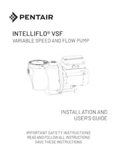
9 Be sure the application of your gear set is the correct oneBREAK-IN PERIOD REQUIRED !-LIGHT DRIVING FOR A PERIOD OF 500 MILES AND NOT AT A CONSTANT ROAD SPEED (50-60 MPH) FOR ANY RATIOS LOWER THAN TOWING FOR EXTENDED SHIMS NEEDED TO GET TO THE REQUIRED PINION DEPTH IN THESE : BFORD 9 ILLUSTRATION: AGM - CHRYSLER DRIVEHEELCOASTTOEILLUSTRATION: CCORRECT LOAD PATTERNILLUSTRATION: DINCORRECT PATTERN(COAST SIDE)ILLUSTRATION: EINCORRECT PATTERN(DRIVE SIDE)TORQUE SPECIFICATIONSPLACE SHIMS NEEDED TO GET TO THE RE-QUIRED PINION DEPTH BETWEEN BEARING SUPPORT & DISTANCE FORD 9 RING GEAR BOLTS3/8 x 7/8 RH 55-60 ft-lb3/8 x 3/4 RH 45-50 ft-lb3/8 ALL LH 45-50 ft-lb7/16 ALL 60-65 ft-lb1/2 ALL 100-110 ft-lbCARRIER CAP BOLTS7/16 (5/8 HEAD) 60-65 ft-lb1/2 (3/4 HEAD) 80-85 GEAR warrants that all new parts supplied by RICHMOND GEAR , except as other-wise provided herein, will be free from defects in material and workmanship for the first 6 months or 50,000 miles, whichever occurs first.
10 THIS WARRANTY WILL NOT APPLY IF ANY PART HAS BEEN MODIFIED, DAMAGED, OR IS DEFECTIVE AS A RESULT OF ANY ACCIDENT, MISUSE, USE IN COMPETI-TIVE APPLICATIONS, IMPROPER INSTALLATION , NEGLIGENCE, REPAIR OR PARTS ARE SOLD AS IS , WITHOUT ANY WARRANTY WHATSOEVER. IMPLIED WAR-RANTIES, INCLUDING WARRANTIES OF MERCHANTABILITY OR FITNESS FOR A PARTICULAR PUR-POSE, ARE EXCLUDED. THE ENTIRE RISK AS TO THE QUALITY AND PERFORMANCE OF SUCH PARTS IS WITH THE BUYER. SHOULD SUCH PARTS PROVE DEFECTIVE FOLLOWING THEIR PURCHASE, THE BUYER, AND NOT THE MANUFACTURER, DISTRIBUTOR OR RETAILER, ASSUMES THE ENTIRE COST OF ALL NECESSARY SERVICING OR RICHMOND GEAR parts warranty is voided if the part is used for competition or if it has been make a warranty claim on parts used in non-competitive applications, distributors should con-tact a RICHMOND GEAR distributor for a Return Goods Authorization (RGA) Number.