Transcription of Introduction - crpd-hk.com
1 Introduction This report presents a case study for design of foundation and diaphragm wall works for a redevelopment in the urban area of Kowloon, Hong Kong. There are some interesting aspects of geotechnical design for the project. Intrafor Hong Kong Ltd. (Intrafor) was the specialist contractor for constructing the diaphragm wall and the foundations. Victor Li & Associates Ltd. (VLA) acted as Intrafor s design consultant for the project. Geotechnical designs for the project started in 2007. At that time, the design approach of CIRIA Report C580 (hereafter called the C580 approach) was only recently introduced to Hong Kong for the design of excavations. This project was one of the earliest projects in Hong Kong for which the C580 approach had been adopted. It is also the first design approved by the Buildings Department in which the risk management approach was applied within the framework of the C580 approach for mitigating the risk against progressive failure of struts.
2 Another interesting feature of the project is that a subsoil drainage layer was constructed beneath the basement slab to reduce the uplift pressure of the basement in order to remove the need for tension piles for anchoring the deep basement. Some aspects of the project have already been published by the authors in a paper of the 2010 HKIE Geotechnical Division Annual Seminar (Liu et al, 2010). This technical note is an expanded version of this paper, repeating some of the contents already published. The paper is written with a special aim to share our experience in using the C580 approach for design of excavation, and hopefully promote wider use of the method. SITE DESCRIPTION AND GROUND CONDITIONS The site is located within the Mass Transit Railway (MTR) protection zone. It is relatively flat with existing ground level at about + It is bounded to the north by Kwun Tong Road, to the east by an existing commercial building supported by bored piles and diaphragm wall, to the south and west by industrial buildings supported by pile foundations.
3 There is a MTR Station and a MTR viaduct structure located about 85m and 15m respectively away from the site. There are existing services and utilities located along the existing road and the service lane outside the site, including water mains, sewer and storm water drains and some cables. The site is a very old reclamation site formed over 40 years ago. Based on the ground investigation records, the site is generally covered in sequence of fill, marine deposit, alluvium and decomposed granite. Bedrock of Grade III or better rock is encountered at to The groundwater monitoring records indicate that the groundwater level varies from to + DETAILS OF DIAPHRAGM WALL AND FOUNDATION WORKS A diaphragm wall cofferdam was proposed for the new basement of the redevelopment. The diaphragm would serve as the embedded wall for supporting the excavation as well as the permanent basement wall.
4 The layout of the proposed cofferdam is shown in Figure 1. Two cross sections across the site are presented in Figures 2 and 3. The shoring works involve a maximum excavation depth of about 25m to reach the bedrock for the construction of raft footings or isolated footings. The 800mm thick diaphragm wall was constructed within the confines of an existing basement. To enable the diaphragm wall to be built, openings were formed in the basement slab and pile caps of the existing basement. The openings in the existing pile caps were backfilled by mass concrete and the openings in the basement slabs were backfilled by soils during backfilling of the entire existing basement prior to construction of the diaphragm wall. Sheetpiles cofferdam had been used when constructing the existing basement. Field investigation confirmed that the sheetpiles were still present in good conditions outside the existing basement.
5 Such existing sheetpiles had provided an effective hydraulic cutoff such that the forming of opening in existing pile caps would not cause hydraulic failure of the soils underneath the existing basement. The diaphragm wall was founded on bedrock. Shear pins were installed at the base of the diaphragm wall to enhance the kick-out stability of the cofferdam. The basement slabs and pile caps of existing basement were demolished during subsequent bulk excavation of the diaphragm wall cofferdam. The construction of diaphragm wall commenced in November 2008 and completed in February 2009, a full-scale pumping test was performed in March 2009 and it confirmed the water tightness of the cofferdam. Bulk excavation for the proposed cofferdam then commenced in April 2009 and reached the final excavation level in September 2009.
6 The whole basement structure was completed successfully in March 2010. There are some interesting points related to the design of the diaphragm wall cofferdam, viz: a. Strutting layout The diaphragm wall was generally supported by a maximum of five layers of struts. At the deepest location of excavation, secondary vertical struts connected to the 5th layer of struts as shown in Figure 2 were installed vertically to provide additional lateral support to the diaphragm wall. In effect, the diaphragm wall cofferdam can be regarded as being supported by 5 layers of struts locally at the position of deepest excavation. b. Pre-installed struts When the concrete for the diaphragm wall was cast, the diaphragm wall would become connected to basement slabs and pile caps of the existing basement.
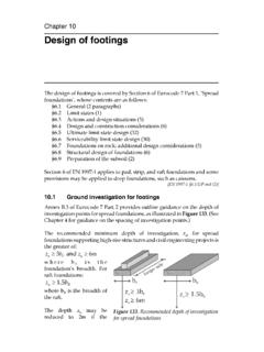
7 The slabs and pile caps of the existing basement would then act as pre-installed struts which helped reduce the deflection of the diaphragm wall during excavation. The presence of such pre-installed struts had been taken into account in the design analysis of the diaphragm wall. The small deflections of the diaphragm wall observed during the bulk excavation works proved that Figure 1 : Layout of cofferdam Figure 2 : Section A-A across the site Figure 3 : Section B-B across the site the existing pile cap and basement slabs were effective in reducing the movement of the diaphragm wall. Footings were used as the foundation scheme for the whole structure. Figure 4 shows the layout of the footings. The site can be divided into two areas.
8 The tower structure of the building is located in Area A and flotation of the footings was not a design concern due to the heavy building loads. The footings in Area A were therefore designed in the usual manner. In Area B, there was only the podium structure. The dead weight of the podium structure was not sufficient to resist the upthrust under normal circumstance. Tension mini-piles were originally adopted as the design scheme. VLA later proposed an alternative scheme of providing a 750mm thick subsoil drainage layer beneath the basement slab over Area B for controlling the uplift pressure to a small design value of 15 kPa. Groundwater entering the site through the base of the diaphragm wall cofferdam would be collected by the subsoil drainage layer, flow towards a basement sump pit and subsequently be discharged by pumping.
9 As the sump pit and the pumping system had to be provided as part of the building drainage system for the new basement, the additional electricity cost and the maintenance costs of the pumping system were found to be less than foundation costs of mini-piles according to life-cycle cost analysis. The use of subsoil drainage layer enabled footings to be also used for as foundation of Area B. When designing the subsoil drainage layer, the inflow rate of water from the bottom of the cofferdam needed to be conservatively assessed and sufficient perforated drainage pipes were provided within the drainage layer to ensure efficient discharge of groundwater to the sump pit such that water pressure would not build up beneath the basement slab. Figure 5 shows the layout of perforated pipes placed within the subsoil drainage layer for conveying the groundwater to the basement sump pit for this project.
10 Relief wells are also provided at the basement slab to allow release of water pressure in the event that the uplift pressure exceeds the design value of 15 kPa. c. Pumping tests In Hong Kong, it is common to use standpipes in observation wells as a means for gauging the drop in water level within the cofferdam during a pumping test. Due to the presence of the existing pile cap, marine deposit and alluvial deposits within the site, the lowering of the groundwater level to the final excavation level was expected to be a very slow process. It was decided to install piezometers in lieu of standpipes for monitoring the performance of pumping test. During the pumping test, the piezometric pressure at various piezometers within the cofferdam dropped very quickly in response to pumping while the piezometeres outside the site did not show any significant drop in piezometric level.