Transcription of Introduction - Quarter Wave
1 Simple Sizing of the Components in a Baffle Step Correction Circuit By Martin J. King, 2/24/04 (revised 7/23/05) Copyright 2005 by Martin J. King. All Rights Reserved. Page 1 of 7 Introduction : Over the past few years, I have become very aware of the baffle step response phenomenon associated with drivers mounted in rectangular shaped baffles. My first Quarter wavelength designs suffered from a relatively depressed bass response and a dominating midrange and high end response. Shortly after completing my ML TQWT speaker article, I started to get private e-mails pointing out the possibility of a baffle step diffraction problem inherent in the design. I received several recommendations for changing the shape and size of the front baffle to push the frequency at which the sound field transitions from radiating into 4 space to radiating into 2 space lower in the frequency range. The method that I have been using to solve the baffle step response problem is the addition of a passive correction filter between the amp and the speaker.
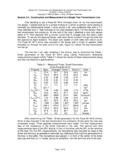
2 The intent of this short document is to describe baffle step response and present the equations required to size an appropriate passive correction filter. Simulation Results : When using most simple speaker design programs, one of the fundamental assumptions is that the speaker is radiating into 2 space. Figure 1 shows a typical plotted response, calculated using one of my MathCad worksheets, for a driver mounted in a bass reflex enclosure. Most other programs available on the Internet would yield a similar result. Figure 1 : Typical Computer Simulation of a Bass Reflex Speaker The predicted SPL response is fairly flat and approximately 90 dB/watt/m at frequencies above 50 Hz. An inexperienced DIY speaker builder might mistakenly assume that if the enclosure is built per the program s modeled dimensions, that the SPL response will be very good. The only way that this simulation would be accurate is if the front baffle of the speaker enclosure were extremely wide and tall, in essence an infinite baffle, so the sound radiates only in front of the speaker enclosure.
3 The subscript IB is used to denote the SPL produced by a speaker mounted in an infinite baffle radiating into 2 space. Simple Sizing of the Components in a Baffle Step Correction Circuit By Martin J. King, 2/24/04 (revised 7/23/05) Copyright 2005 by Martin J. King. All Rights Reserved. Page 2 of 7 The other extreme for simulating speaker performance assumes that the speaker enclosure is suspended and radiating into 4 space or free space. Free space implies that no reflective surfaces such as a wall, a floor, or a ceiling are close enough to influence the SPL response. At low frequencies the sound radiates equally in front and behind the speaker enclosure. The blue curve in Figure 2 depicts the SPL response, again calculated using one of my MathCad worksheets, of the same bass reflex enclosure design suspended in free space. For reference, the infinite baffle case, from Figure 1, is still shown as the red curve.
4 The subscript FS is used to denote the SPL produced by a speaker radiating into free space. Figure 2 : Computer Simulation of a Bass Reflex Speaker Radiating into Free Space In Figure 2, the difference between the SPL curves is easily seen at low frequencies. There is a 6 dB SPL loss below 100 Hz for the speaker radiating into free space compared to the speaker mounted in an infinite baffle. The speaker radiating into free space has an unbalanced SPL response. The bass frequencies arrive at the listening position with half the volume level compared to the midrange and high frequencies. Words typically used to describe the sound of this type of speaker response are shouty, harsh, and fatiguing. At first a listener might be fooled into thinking that this speaker response is extremely detailed and revealing. It can be an alluring sound for a while, but usually after extended listening it becomes difficult to take. I can speak from personal experience.
5 Looking again at Figure 2, it is also apparent that as frequency increases from 100 Hz to 500 Hz the responses of the two simulations converge. A speaker radiating into 2 space or 4 space produces essentially the same volume of midrange output at the listening position. As frequency increases, the wavelength of sound decreases until eventually the size of the front baffle is big enough to be considered an infinite baffle. This transition from radiating into 4 space to radiating into 2 space, and the theoretical 6 dB gain in SPL output at the listening position, is referred to as the baffle step response phenomenon. All practical speaker designs have this problem over some frequency range. For a speaker system radiating into free space, the SPL of the midrange frequencies compared to the SPL of the low bass frequencies can in theory present a 6 Simple Sizing of the Components in a Baffle Step Correction Circuit By Martin J.
6 King, 2/24/04 (revised 7/23/05) Copyright 2005 by Martin J. King. All Rights Reserved. Page 3 of 7 dB SPL mismatch at the listening position. However, in the home environment the reality falls someplace between an infinite baffle and a free space SPL response. The theoretical 6 dB SPL mismatch is really more like 3 to 4 dB once the room s reinforcement of the bass frequencies through reflections from the floor, the walls, and the ceiling are taken into account. Method of Calculation : From a given driver s Thiele / Small parameters, the SPL/watt/m can be determined. For example, a typical 8 inch diameter mid-bass might be listed by the manufacturer as being 90 dB efficient. Manufacturers typically measure their driver s response in 2 space using a very large baffle. If the same driver were placed in a typical rectangular enclosure and mounted in free space, the measured efficiency for the driver below the baffle step transition would be 84 dB (90 dB 6 dB).
7 The efficiency would then increase to 90 dB as the baffle step phenomenon comes into play for the midrange and high frequencies. The frequency midpoint of this transition from 4 space to 2 space can be estimated using the following relationship. f3 = 4560 / WB where WB = width of the baffle in inches Correcting for the baffle step loss at low frequencies can be handled in several ways. One solution would be to extend the baffle width WB to a very large value pushing the transition frequency below the systems operating range. This would lead to an extremely large baffle with no loss in driver efficiency. A second method would be applied in a two way design by placing the crossover point in the baffle step transition region and padding down the SPL output from the midrange driver and/or the tweeter driver. A third method is to apply a passive filter between the amplifier and the driver as shown by the schematic in Figure 3 at the top of the following page.
8 I have used the third method in all of my full range speaker designs and found it to be a very simple, elegant, and powerful tool for rebalancing the SPL response across the entire frequency range. There are different ways to design the filter shown in Figure 3. In the past, I used the finished speaker s measured impedance and SPL response as input into a MathCad worksheet for simulating the impact of the circuit and iterating to find an initial filter design. Then after the filter is constructed and installed, I fine tune the values by listening to the speaker located in my room. Listening is always the final proof test. But most DIY speaker builders do not have the measurement tools required to design the baffle step correction circuit this way. Recently, I put together a simple calculation to be used as a sanity check on my MathCad simulations. It also occurred to me that this simple calculation method might be helpful for others looking to size baffle step correction circuits.
9 Based on the final listening results from recently completed speakers, I have found these sizing calculations to be fairly accurate and require minimal component adjustments once the circuit is constructed and installed. Simple Sizing of the Components in a Baffle Step Correction Circuit By Martin J. King, 2/24/04 (revised 7/23/05) Copyright 2005 by Martin J. King. All Rights Reserved. Page 4 of 7 Figure 3 : Schematic of a Baffle Step Correction Circuit LBSCRZ obelDriver + - + -CZobelegRparallel There are two parts to the circuit schematic shown above. First, there is a Zobel correction circuit placed across the driver s input terminals to flatten out any rising impedance due to the voice coil inductance. Generally accepted equations for sizing the Zobel circuit components are shown below. RZobel = x Re ohms CZobel = Lvc / ( x Re)2 farads where Re = driver s DC resistance in ohms Lvc = driver s voice coil impedance in henries The second part is the baffle step correction circuit consisting of the components denoted by LBSC and Rparallel in the schematic shown in Figure 3.
10 To calculate the values of these two components, the following equations are provided. f3 = 4560 / WB Hz Rparallel = Re x (10dB/20 -1) ohms LBSC = Rparallel / (2 x x f3) henries where WB = width of the baffle in inches Re = driver s DC resistance in ohms Simple Sizing of the Components in a Baffle Step Correction Circuit By Martin J. King, 2/24/04 (revised 7/23/05) Copyright 2005 by Martin J. King. All Rights Reserved. Page 5 of 7 = dB = amount of attenuation required The value calculated for Rparallel is a function of the amount of baffle step attenuation desired in dB. The formula for the inductor has changed from the one given in the original version of this document. Seth Murray, of Arpeggio Music in McMinnville Oregon, pointed out that Rparallel and LBSC have to be related to keep the midpoint frequency constant. If Rparallel is adjusted to provide a different amount of baffle step correction the value of LBSC must also change to maintain the same frequency midpoint.