Transcription of Introduction to coaxial cables - rf-microwave.com
1 Elettronica di Rota F. tel ++ 48 75 15 fax ++ 48 92 76 coaxial cables , for RF - WAVE - VARIOUS pag J 1 Here follows some informations useful to understand the basic concepts about coaxial cables , with the tricks of the trade and curious informations that are rare to find on school books and manufacturers catalogs. Introduction to coaxial cables Perhaps none of us have never thought that the development of radio communications would never have been possible without the invention of coaxial cable , it is continuously used in our applications that we don t think about that. The attribution of the invention of coaxial cable is complex and contrasted, there are several American and European patents already near the end of 800 (the first patent is in 1880 by O. Heaviside UK) the discovery is then fell into obscurity for many years because surely there was nothing to make pass in a coaxial cable !
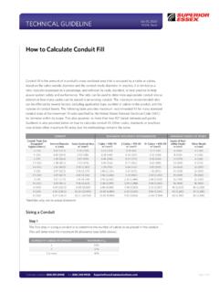
2 ! The real discovery and its actual use dates back to 1929 due to the need for a more efficient and with less interferences conductor for the transmissions of many telephone channels on a single "carrier". In the early 30s, this technique was also advantageously used for the first experiments with the emerging television and so on until today. The drawing below shows all the transmission lines used in RF, from KHz to GHz, the coaxial cable line is the most used and most cost-effective, it can be used by up to 110 GHz with the current technology. coaxial bifilar wave microstrip stripline cable cable guide transmission lines used for RF To better understand the characteristics of a coaxial cable it is also necessary to know all the parameters associated with it, for reasons of space we will cover just some of the most important that are.
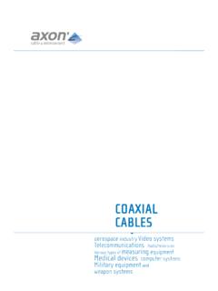
3 Impedance - Attenuation - Cut-off frequency and optimal frequency Max handling power - Return Loss - Propagation velocity IMPEDANCE The impedance of a coaxial line (over about 1 MHz) depends only on the type of dielectric used, or by the dielectric constant r, and the ratio between the diameter of the inner conductor and the inner diameter of the outer screen (not the size) and it is independent of the length and frequency. But why are there 50 and 75 cables ? From the graph at side we can see clearly that the lowest attenuation is achieved at about 75-77 of impedance and the maximum power handling ataround 30 (with cables of same size). The Navy during World War II decided to take the value of 52 as a compromise between attenuation and maximum power (then rounded to 50 ). With the birth of television, it was decided instead to adopt the value of 75 because it ensured the minimum attenuation, because in air TV reception there is no power along the cables .
4 Given the primordial TV receivers systems, VHFat fist an than UHF, and the high attenuation, it was definitely the right choice. Ratio between the diameter of the inner and outer conductor for the impedance of 50 and 75 with various dielectricsimpedance Air r 1 Polyethylene r 2,3 Teflon r 2,04 Foam r ~ 1,5 50 2,3 3,5 2,8 75 3,5 6,6 6 4,6 The standardization to 50 was a decisive step because already in Europe in the early post war, Germany took the value of 60 thinking it was the right choice because it is a half way between 50 and 75 . The standardization to 50 was very important, as at each side of the cable it has to plug something, or rather a lot of "things" that have to be standardized to 50 too.
5 In addition to the 50 and 75 cables there are also some strange and particular values, let s see what they are: - and 25 cables : for transformer and matching of power stages, eg. FET push-pull and / or broadband. - 35 cables : for the production of hybrid couplers, it is used also to match impedance at / 4 between 50 and 25 (25 is the result of two 50 in parallel). - 70 cables : to build Wilkinson combiners. These cables are usually available in rigid or handy-form semi-rigid configuration in order to obtain the best performance being used in particularly critical or high power stages. ATTENUATION The attenuation, after the impedance, is the most important discriminating in the choice of a coaxial cable , it is linearly proportional to the length of the cable in fact it is measured in dB / meter. The attenuation depends on the goodness of Formula for calculating the impedance dD rZlog138 = elettronica di Rota F.
6 Tel ++ 48 75 15 fax ++ 48 92 76 coaxial cables , for RF - WAVE - VARIOUS pag J 2 dielectric, on the physical size and on the skin effect of the conductors, so it is intuitive that the lowest attenuation occurs with large cables and with air dielectric. The air dielectric is very complicated to implement and it is generally used only for TV or radio broadcast where the power is impressive, moreover these cables require vacuum pumps to prevent contamination by external agents of the air dielectric (moisture and condensation). A very cheap way to reduce loss consists of injecting an inert gas (nitrogen) in the dielectric to obtain a dielectric constant as close as air, this is often done with foam cables but also with teflon ones. The addition of gas contribute also for a more long-term stability of the cable parameters even under critical conditions like moisture and temperature changes.
7 The choice of dielectric is important to have less losses in the cable , in fact with teflon dielectric the insertion loss is less than with the classic polyethylene, but the true breakthrough in terms of attenuation is achieved only with expanded dielectric, whether it is foam or teflon. The attenuation for skin effect of the conductor is equal to the square root of frequency and with a silver plated conductor it is slightly improved the attenuation. As a general rule skin effect loss dominates from low to mid frequencies and dielectric loss dominates at high frequencies. The propagation characteristics of surface due to skin effect is used in some cables as an economic advantage because it is possible to use poorer or cheaper conductor, with coatings such as copper or silver, that s because low attenuation cables have a tubolar copper or solid copper plated aluminium internal conductor.
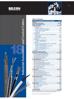
8 DC audio (1 KHz) 1 MHz 1 GHz skin effect at different frequencies SKIN EFFECT by rising in frequency the resistance of the cable increases because the current flows only on the outer part (the outer conductor) and only on the inside (regarding the shield) Obviously, increasing the size of the coaxial cable there is less attenuation up to the cut-off frequency. The outer shield too increase the attenuation but its contribution is always smaller than the other two factors. In fact, a little-known aspect to consider is the layer of outer conductor that acts as a shield, if this is too small there is greater attenuation caused by the loss of signal due to radiation, that is for a not good shielding of the cable (see RG 58). A small contribution to the increase of losses is also due to using an inner conductor composed of many wires, if this technique improves the flexibility of the cable , however, it introduces a very small increase in losses of around 5%.
9 CUT-OFF FREQUENCY - MAX OPTIMAL FREQUENCY The cut-off frequency of a coaxial cable is not to be confused with the maximum frequency where it is "convenient" to use a particular cable . A given cable makes sense to be used up to a certain frequency (sometimes recommended by the manufacturer and referred as "operating frequency") simply because up to that frequency parameters are quite suitable for its use, at same frequency the same cable can t be used for different applications. For example in microwave radio links wirings, even at 20 GHz, are used handy-form cables 10 to 30 cm long for internal interconnections, it will not be possible to use the same cable for antenna connection, 10 or 20 m at the same frequency, since for such long distances the attenuation would be too high, these cables are not suitable for outdoor use.
10 When choosing a cable is often not considered the factor of insulation that depends on the shielding of the outer conductor, for example in a wiring inside of a VHF or UHF radio link is not acceptable to use a single shield cable , with the risk of RF coupling between Tx and Rx undermining the goodness of a good duplexer filter with 80 dB of insulation between Tx and Rx, in fact, the coupling between two RG58 cables that pass parallel for 3 or 4 cm have an insulation of only 70-75 dB. So in the choice of a cable must be considered about ten different factors, many of which are in conflict with each other. The cut-off frequency represents instead the maximum absolute frequency of use, and over of that there are various resonances that change the phase and amplitude in the propagation of electromagnetic waves in the cable itself. The propagation in a coaxial cable is defined as TEM (Transversal Electric and Magnetic Field), the electric and magnetic field lines are perpendicular to the cable .