Transcription of Introduction to J1939 - Vector
1 Introduction to J1939 . Version 2010-04-27. Application Note AN-ION-1-3100. Author(s) Markus Junger Restrictions Public Document Abstract This application note presents an overview of the fundamental concepts of J1939 in order to give a first impression. Table of Contents Overview ..2. Parameter Groups ..3. Interpretation of the CAN Parameter Group Suspect Parameter Number (SPN)..4. Special Parameter Groups ..4. Network Address Claiming Procedure ..5. Request for Address Claim ..6. Address Capability ..7. Transport Diagnostics ..9. Additional Sources ..10. Contacts ..11. 1. Copyright 2010 - Vector Informatik GmbH. Contact Information: or ++49-711-80 670-0. Introduction to J1939 . Overview SAE J1939 is used in the commercial vehicle area for communication in the commercial vehicle. In this application note, the properties of SAE J1939 should be described in brief. SAE J1939 uses CAN (Controller Area Network, ISO11998) as physical layer.
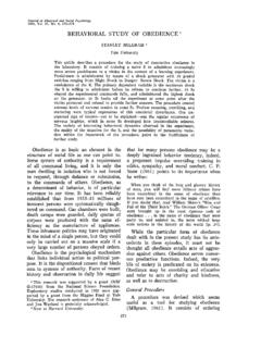
2 It is a recommended practice that defines which and how the data is communicated between the Electronic Control Units (ECU) within a vehicle network. Typical controllers are the Engine, Brake, Transmission, etc. Figure 1: Typical J1939 vehicle network The particular characteristics of J1939 are: Extended CAN identifier (29 bit). Bit rate 250 kbit/s Peer-to-peer and broadcast communication Transport protocols for up to 1785 data bytes Network management Definition of parameter groups for commercial vehicles and others Manufacturer specific parameter groups are supported Diagnostics features There exist several standards which are derived from SAE J1939 . These standards use the basic features of SAE. J1939 with a different set of parameter groups and modified physical layers. These standards are: ISO11783 Tractors and machinery for agriculture and forestry Serial control an communication Defines the communication between tractor and implements on an implement bus.
3 It specifies some services on application layer, like Virtual Terminal, Tractor ECU, Task Controller and File Server. It adds an Extended Transport Protocol and Working Set Management. NMEA2000 Serial-data networking of marine electronic devices It defines parameter groups for the communication between marine devices. It specifies the additional Fast Packet transport protocol. ISO11992 Interchange of digital information between towing and towed vehicle Specifies the interchange of information between road vehicle and towed vehicle. It uses same parameter group format as J1939 on a different physical layer with 125 kbit/s. FMS Fleet Management System The FMS standard defines a gateway between the J1939 vehicle network and a fleet management system. 2. Application Note AN-ION-1-3100. Introduction to J1939 . Parameter Groups A parameter group is a set of parameters belonging to the same topic and sharing the same transmission rate.
4 The definition of the application relevant parameter groups and parameters can be found in application layer document [9]. The length of a parameter group is not limited to the length of a CAN frame. Usually a parameter group has a minimum length of 8 bytes up to 1785 bytes. Parameter groups with more than 8 bytes require a transport protocol for transmission. Interpretation of the CAN Identifier The CAN identifier of a J1939 message contains Parameter Group Number (PGN), source address, priority, data page bit, extended data page bit and a target address (only for a peer-to-peer PG). The identifier is composed as follows: Extended PDU PDU Source Priority Data Page Data Page Format Specific Address 3 bit 1 bit 1 bit 8 bit 8 bit 8 bit With PDU format < 240 (peer-to-peer), PDU specific contains the target address. Global (255) can also be used as target address. Then the parameter group is aimed at all devices.
5 In this case, the PGN is formed only from PDU format. With PDU format >= 240 (broadcast), PDU format together with the Group Extension in the PDU specific field forms the PGN of the transmitted parameter group. Parameter Group Number Each parameter group is addressed via a unique number the PGN. For the PGN a 24 bit value is used that is composed of the 6 bits set to 0, PDU Format (8 bits), PDU Specific (8 bits), Data Page (1 bit) and Extended Data Page (1 bit). There are two types of Parameter Group Numbers: Global PGNs identify parameter groups that are sent to all (broadcast). Here the PDU Format, PDU. Specific, Data Page and Extended Data Page are used for identification of the corresponding Parameter Group. On global PGNs the PDU Format is 240 or greater and the PDU Specific field is a Group Extension. Specific PGNs are for parameter groups that are sent to particular devices (peer-to-peer). Here the PDU.
6 Format, Data Page and Extended Data Pare are used for identification of the corresponding Parameter Group. The PDU Format is 239 or less and the PDU Specific field is set to 0. 3. Application Note AN-ION-1-3100. Introduction to J1939 . With this breakdown of the PGN, 240 + (16 * 256) = 4336 different parameter groups within each data page are possible. With the transmission of a parameter group, the PGN is coded in the CAN identifier. With the Data Page bit and Extended Data Page bit 4 different data pages can be selected, see following table. Extended Data Data Page Bit Description Page Bit 0 0 SAE J1939 Page 0 Parameter Groups 0 1 SAE J1939 Page 1 Parameter Groups (NMEA2000 ). 1 0 SAE J1939 reserved 1 1 ISO 15765-3 defined Table 1: Data Pages Sample of a parameter group definition: Name: Engine temperature 1 ET1. Transmission rate: 1s Data length: 8 bytes Extended Data Page 0. Data page: 0. PDU format: 254. PDU specific: 238.
7 Default priority: 6. PG Number: 65,262 (00 FEEE16). Description of data: Byte: 1 Engine Coolant Temperature 2 Engine Fuel Temperature 1. 3,4 Engine Oil Temperature 1. 5,6 Engine Turbocharger Oil Temperature 7 Engine Intercooler Temperature 8 Engine Intercooler Thermostat Opening Suspect Parameter Number (SPN). A suspect parameter number is assigned to each parameter of a parameter group or component. It is used for diagnostic purpose to report and identify abnormal operation of a Controller Application (CA). The SPN is a 19 bit number and has a range from 0 to 524287. For proprietary parameters a range from 520192 to 524287 is reserved. Special Parameter Groups SAE J1939 -21 defines some parameter groups on the data link layer: Request parameter group The request parameter group (RQST, PGN 00EA0016) can be sent to all or a specific CA to request a specified parameter group. The RQST contains the PGN of the request parameter group.
8 If the receiver of a specific request cannot respond, it must send a negative acknowledgment. The RQST has a data length code of 3 bytes and is the only parameter group with a data length code less than 8 bytes. Acknowledgement parameter group The acknowledgement parameter group (ACKM, PGN 00E80016) can be use to send a negative or positive acknowledgment, in response to a request. 4. Application Note AN-ION-1-3100. Introduction to J1939 . Address claiming parameter group The address claiming parameter group (ACL, PGN 00EE0016) is used for network management, see chapter Commanded address parameter group The commanded address parameter group (CA, PGN 00 FED816) can be used to change the address of a CA. Transport protocol parameter group The transport protocol parameter groups (TPCM, PGN 00EC0016 and TPDT, PGN 00EB0016) are used to transfer parameter groups with more than 8 data bytes, see chapter Network Management The software of an Electronic Control Unit (ECU) is the Controller Application (CA).
9 An ECU may contain one or more CAs. Each CA has a unique address and an associated device name. Each message that is sent by a CA contains this source address. There are 255 possible addresses: Valid source addresses for CAs and Used for CAs with Preferred Addresses and defined functions Available for all CAs 254 Null 255 Global Most CAs like Engine, Gearbox, etc. have a preferred address (see [2]). Before a CA may use an address, it must register itself on the bus. This procedure is called "address claiming." Thereby the device sends an "Address Claim" parameter group (ACL, PGN 00EE0016) with the desired source address. This PG contains a 64-bit device name. If an address is already used by another CA, then the CA whose device name has the higher priority has claimed the address. The device name contains some information about the CA and describes its main function. A manufacturer code must be requested by the SAE.
10 The values of the fields are defined in SAE J1939 -81 [11]. Figure 2: Device name data of the address claim parameter group Address Claiming Procedure In a common situation the controller application sends an Address Claim parameter group at start up and waits a defined amount of time. If it does not detect an address conflict it can start with its normal communication. 5. Application Note AN-ION-1-3100. Introduction to J1939 . Figure 3: Address claiming procedure In a situation where another CA already uses the address an address conflict occurs. The CA with the higher priority of the device name will obtain the address. The other CA must send a Cannot Claim Address parameter group, with source address Null (254). Figure 4: Address claiming procedure with address conflict It depends on the address capability of a CA how to proceed, if an address cannot be obtained. Request for Address Claim A CA can detect other CAs in the network by requesting the ACL parameter group.