Example: barber
Introduction to the Design Process - University of Florida
eving the score of 10 (out of 10), and the score for the welded plate design was computed as $2200 / $2500 * 10.0 = 8.8. Magnitude is the assigned value of each objective, whether quantitative or qualitative. Score is the relative comparison of the different magnitudes.
Tags:
Information
Domain:
Source:
Link to this page:
Documents from same domain
S. L. ten Cate 08-2015 - University of Florida
mae.ufl.eduThe most common types of pipe thread are: • NPT - American Taper Pipe Thread = National Pipe Taper • NPTF - American Taper Pipe Thread for Dryseal joint without sealant compound = National Pipe Taper Fuel NPT and NPTF appear to be identical. Both have the same pitch diameter at the top of the hole of the internal thread or end of the pipe ...

Fundamental Principles of Mechanical Design
mae.ufl.eduMechanical Design Fundamentals K. Craig 20 Laws of Nature • To develop a physical model of an existing system or of a system concept, we use engineering judgment and make simplifying assumptions. • To develop a mathematical model, a model that can predict system dynamic behavior, we apply the Laws of Nature to the physical model.

Useful Motor/Torque Equations for EML2322L
mae.ufl.eduCalculate the Torque required to lift the Force with the lever arm . T = F x d = 49.05 N x 0.5 m = 24.525 N-m . We cannot perform the lift with this set-up, because the stall torque is smaller than . the torque required for the lift. We must either shorten the length of the lever arm,
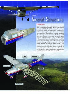
Chapter 2 Aircraft Structure
mae.ufl.edustructure constructed of wood, steel, or aluminum tubing. [Figure 2-5] The most popular types of fuselage structures used in today’s aircraft are the monocoque (French for “single shell”) and semimonocoque. These structure types are discussed in more detail under aircraft construction later in the chapter. Wings

Drive Wheel Motor Torque Calculations
mae.ufl.eduDrive Wheel Motor Torque Calculations . Step Four: Determine Total Tractive Effort . The Total Tractive Effort (TTE) is the sum of the forces calculated in steps 1, 2, and 3. (On higher speed vehicles friction in drive components may warrant the addition of 10%-15% to the total tractive effort to ensure acceptable vehicle performance.)
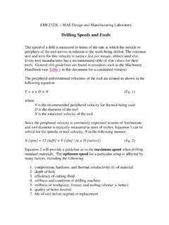
Drilling Speeds and Feeds - University of Florida
mae.ufl.eduEquation 2 will provide a guideline as to the maximum speed when drilling standard materials. The optimum speed for a particular setup is affected by many factors, including the following: 1. composition, hardness, and thermal conductivity (k) of material 2. depth of hole 3. efficiency of cutting fluid 4. stiffness and condition of drilling ...

CHAP 4 FINITE ELEMENT ANALYSIS OF BEAMS AND FRAMES
mae.ufl.edu1 CHAP 4 FINITE ELEMENT ANALYSIS OF BEAMS AND FRAMES 2 INTRODUCTION • We learned Direct Stiffness Method in Chapter 2 – Limited to simple elements such as 1D bars • we will learn Energy Methodto build beam finite element – Structure is in equilibrium when the potential energy is minimum

Engineering Change Notice - University of Florida
mae.ufl.eduEngineering Change Notice Definition . An . Engineering Change Notice (ECN) is a document authorizing and recording design changes throughout the prototyping and life-cycle phases of a product. ECN documentation contains the ... The drawings must clearly show the detail(s) affected by the change. ...

Tap & Drill Chart
mae.ufl.eduDrill Size Dec. Eq. Drill Size Dec. Eq. Drill Size Dec. Eq. Drill Size Dec. Eq. 0 0.060 80 0.045 3/64 0.047 55 0.052 52 0.064 50 0.070 64 0.054 53 0.060 1/16 0.063

Engineering Design Representation
mae.ufl.eduExternal threads refers to threads cut or rolled into the external cylindrical surface of a fastener or stud. The size most commonly associated with screw threads is the nominal diameter. Nominal diameter is a more of a label than a size. For example, a bolt and nut
Related documents
VW2100 Vibrating Wire Piezometer Instruction Manual
rstinstruments.comAug 27, 2020 · The Vibrating Wire sensors are made of two small diameter cylindrical parts joined by a length of steel tubing. The diaphragm is welded to the front cylinder. A high strength steel wire (the Vibrating Wire) is clamped to the center of the diaphragm, then is run through the first cylinder, and then clamped to the base of the second

Safe Rigging Practices - ocfl.net
apps.ocfl.netDamaged, Distorted or Field Welded Hooks. Damaged or Worn End Attachments. If In Doubt, Don’t Use It! Definitions Balanced – load equally distributed on each side of ... To guard against failure of a wire rope in service, the actual load on the rope should only be a fraction of the breaking strength.

Welding Qualification/Certification
spot.pcc.eduMake sure your slag hammer and wire brush are in good condition. 5. Plan the weld carefully to avoid having to patch up low spots. Decide before you strike the arc the size and location of the bead you are about to run. If the weld fill becomes uneven, fix it immediately by filling in the low areas, don't wait until the flush layer or cover ...

ACI 318-11 to ACI 318-14 and ACI 318.2-14 Building Code ...
www.concrete.orgTransition Key: 318‐11 to 318‐14 Building Code Requirements for Structural Concrete 318‐11 318‐14 Note Description 2.1 2.2 ‡ Heading: Code notation A2 A2 ~ Revised notation f'cr ‐‐‐ ~ Reference to ACI 301 replaced this notation ft ft ~ Revised notation Mslab Msc ~ Revised notation M1 M1 ~ Changed sign convention Pn Pn ~ Added tensile strength requirements for concrete