Transcription of Introduction to Three-phase Circuits
1 1 Introduction to Three-phase CircuitsBalanced 3-phase systemsUnbalanced 3-phase systems2 Introduction to 3-phase systemsSingle-phase two-wire system: Single source connected to a load using two-wire systemSingle-phase three-wire system: Two sources connected to two loads using three-wire system Sources have EQUAL magnitude and are IN PHASE3 Balanced Two-phase three-wire system: Two sources connected to two loads using three-wire system Sources have EQUAL frequency but DIFFFERENT phasesCircuit or system in which AC sources operate at the same frequency but different phases are known as Phase System: A generator consists of two coilsplaced perpendicular to each other The voltage generated by one lags the other by 90 .4 Balanced Three-phase four-wire system: Three sources connected to 3 loads using four-wire system Sources have EQUAL frequency but DIFFFERENT phasesThree Phase System: A generator consists of three coilsplaced 120 apart. The voltage generated are equal in magnitude but, out of phase by 120.
2 Three phase is the most economical Generation Three things must be present in order to produce electrical current:a)Magnetic fieldb)Conductorc)Relative motion Conductor cuts lines of magnetic flux, a voltage is induced in the conductor Direction and Speed are importantGENERATING A SINGLE PHASEM otion is parallel to the flux. No voltage is is 45 to voltage is of A SINGLE PHASEGENERATING A SINGLE PHASExNSMotion is perpendicular to flux. Induced voltage is A SINGLE PHASEM otion is 45 to voltage is of A SINGLE PHASENSM otion is parallel to flux. No voltage is A SINGLE PHASENSN otice current in the conductor has is of is 45 to flux. GENERATING A SINGLE PHASENSM otion is perpendicular to flux. Induced voltage is A SINGLE PHASENSM otion is 45 to flux. Induced voltage is of A SINGLE PHASEM otion is parallel to voltage is to produce another OF Three-phase ACNxxS Three Voltages will be induced across the coils with 120 phase differencePractical THREE PHASE GENERATOR The generator consists of a rotating magnet (rotor) surrounded by a stationary winding (stator).
3 Three separate windings or coils with terminals a-a , b-b , and c-c are physically placed 120 apart around the stator. As the rotor rotates, its magnetic field cuts the flux from the three coils and induces voltages in the coils. The induced voltage have equal magnitude but out of phase by 120 . Three-phase WAVEFORMP hase 2lags phase 1by 120 .Phase 2leads phase 3by 120 .Phase 3lags phase 1by 240 .Phase 1leads phase 3by 240 .Phase 1 Phase 2 Phase 3120 120 120 240 120 120 120 240 18 ALL electric power system in the world used 3-phase system to GENERATE, TRANSMIT and DISTRIBUTE One phase, two phase, or three phase icanbe taken from three phase system rather than generated WE STUDY 3 PHASE SYSTEM ? Instantaneous power is constant (not pulsating). thus smoother rotation of electrical machines High power motors prefer a steady torque More economical than single phase less wire for the same power transfer The amount of wire required for a three phase system is less than required for an equivalent single phase systemsGeneration, Transmission and Distribution203-phase systemsGeneration, Transmission and Distribution21Y and connectionsBalanced 3-phase systems can be considered as 3 equal single phase voltage sources connected either as Y or Delta ( ) to 3 single three loads connected as either Y or SOURCE CONNECTIONSLOAD CONNECTIONSY connected source connected sourceY connected load connected loadY-Y Y- -Y - 22 Balance Three-phase Sources Two possible configurations: Three-phase voltage sources: (a) Y-connected.
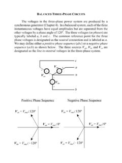
4 (b) -connected23 Balanced 3-phase systemsYconnectionbcLOAD CONNECTIONS anbcaZ1Z2Z3 ZaZbZc connectionBalanced load: Z1= Z2 = Z3= ZYZa= Zb = Zc= Z 3Y ZZUnbalanced load: each phase load may not be the + VanVbnVcnanbcPhase sequence )tcos(V2)t(vpan )120tcos(V2)t(vopbn )120tcos(V2)t(vopcn opbn120V Vopcn120V Vopan0V V VbnVanVcn120o240oRMS phasors !The phase sequenceis the time orderin which the voltages pass through their respective maximum Vopbn120V Vopcn120V V120o120o120oPhase sequence : Vanleads Vbnby 120oand Vbnleads Vcnby 120o This is a known as abc sequenceor positive sequence + VanVbnVcnanbcPhase Sequence26opan0V Vopcn120V Vopbn120V V120o120o120oPhase sequence : Vanleads Vcnby 120oand Vcnleads Vbnby 120o This is a known as acbsequenceor negative sequenceWhat if different phase sequence ? phase sequence )cos(2)(tVtvpan )120tcos(V2)t(vopcn )120tcos(V2)t(vopbn opcn120V Vopbn120V Vopan0V V RMS phasors !VbnVanVcn120o240oSolution:The voltages can be expressed in phasor form asWe notice that Vanleads Vcnby 120 and Vcnin turn leads Vbnby 120.
5 Hence, we have Determine the phase sequence of the set of voltages.)110cos(200)230cos(200)10cos(20 0 tvtvtvcnbnan V 110)2/200(VV 230)2/200(VV 10)2/200(V cnbnan28 Balanced 3-phase Y-Y Line current = phase currentopan0V Vopbn120V Vopcn120V VIaZYZYZY+ VanVbnVcnnbcaInIbIcNACBYopaZ0V IYopbZ120V IYopcZ120V IPhase voltagesline currentsopopopnbannnbabaabVVVVVVVVVVV303 600 Vopncbnbc90V3VV Vopnacnca150V3VV Vline-line voltagesORLine voltages0ncba IIIIThe wire connecting n and N can be removed !measured between the neutraland any line(line to neutral voltage)29 Balanced 3-phase systemsBalanced Y-Y Connectionopopopnbanab30V360V0 VVV V30 Balanced 3-phase systemsBalanced Y-Y Connectionopopopnbanab30V360V0 VVV VanVbnVcnV31 Balanced 3-phase systemsBalanced Y-Y ConnectionnbVanVopopopnbanab30V360V0 VVV V32 Balanced 3-phase systemsBalanced Y-Y ConnectionnbVanVopncbnbc90V3VV VncVbnVopopopnbanab30V360V0 VVV V33 Balanced 3-phase systemsBalanced Y-Y Connectionopncbnbc90V3VV Vopnacnca150V3VV VnbVanVncVbnVnaVcnVopopopnbanab30V360V0 VVV V34 Balanced 3-phase systemsBalanced Y-Y Connectionopncbnbc90V3VV Vopnacnca150V3VV VpLV3V abVbcVcaVo30o30o30cnVbnVanVcabcabLVVVV whereandcnbnanpVVVV Line voltage LEADS phase voltage by 30oopopopnbanab30V360V0 VVV V35 Balanced 3-phase systemsBalanced Y-Y ConnectionFor a balanced Y-Y connection, analysis can be performed using an equivalent per-phase circuit: for phase A.
6 ZYZYZY+ VanVbnVcnnbcaIn=0 IbIcIaACBN36 Balanced 3-phase systemsBalanced Y-Y ConnectionFor a balanced Y-Y connection, analysis can be performed using an equivalent per-phase circuit: for phase A: ZY+ VannaIaBased on the sequence , the other line currents can be obtained from:YanaZVI oab120 IIoac120 IIAN37 Balanced 3-phase systemsBalanced Y- Connectionopan0V Vopbn120V Vopcn120V VPhase currentsIaZ Z Z + VanVbnVcnnbcaIbIcABCAB opab30V3VV ZABABVIBC opbc90V3VV ZBCBCVICA opca150V3VV ZCACAVIU sing KCL,oABoABCAABa303)12011( IIIIIoBCoBCABBCb303)12011( IIIIIoCAc303 IIABIBCICAI38 Balanced 3-phase systemsBalanced Y- ConnectionoABoABCAABa303)12011( IIIIIoBCoBCABBCb303)12011( IIIIIoCAc303 IIABIBCICAIo30o30o30cIbIaIpLI3I Phase current LEADS line current by 30ocbaLIIII whereandCABCABpIIII 39 Balanced 3-phase - opab0V Vopbc120V Vopcn120V VIaZ Z Z VabVbcVcabcaIbIcABCABabVV ZABABVIBCbcVV ZBCBCVICAcaVV ZCACAVIU sing KCL,oABoABCAABa303)12011( IIIIIoBCoBCABBCb303)12011( IIIIIoCAc303 IIABIBCICAI+ Phase currentsline currentsLine-line voltage is the same as phase voltage in - 40 Balanced 3-phase systemsBalanced - ConnectionIaZ Z Z VabVbcVcabcaIbIcABCABIBCICAI+ Alternatively, by transforming the connections to the equivalent Y connections per phase equivalent circuit analysis can be Vopbc120V Vopcn120V V41 Balanced 3-phase systemsBalanced -YConnectionopab0V Vopbc120V Vopca120V VIaVabVbcVcabcaIbIc+ ZYZYZYACBNHow to find Ia?
7 0 ZZbYaYab IIV-Loop1 Loop1 YabbaZVII Since circuit is balanced, Ib= Ia -120o))120(11(oaba IIIoa303 IoYpa30Z3V ITherefore42 Balanced 3-phase systemsBalanced -YConnectionopab0V Vopbc120V Vopca120V VIaVabVbcVcabcaIbIc+ ZYZYZYACBNHow to find Ia? (Alternative)Transform the delta source connection to an equivalent Y and then perform the per phase circuit analysis43 Source ImpedanceLine Impedance A balanced Y-Y system, showing the source, line and load ImpedanceEquivalent Circuit44 Three-phase CircuitsUnbalanced 3-phase systemsPower in 3-phase system45 UNBALANCED DELTA-CONNECTED LOADThe line currents will not be equal nor will they have a 120 phase difference as was the case with balanced FOUR-WIRE, WYE-CONNECTED LOAD On a four-wire system the neutral conductor will carry a current when the load is unbalanced The voltage across each of the load impedances remains fixed with the same magnitude as the line to neutral voltage. The line currents are unequal and do not have a 120 phase THREE-WIRE, WYE-CONNECTED LOAD The common point of the three load impedances is not at the potential of the neutral and is marked "O" instead of N.
8 The voltages across the three impedances can vary considerably from line to neutral magnitude, as shown by the voltage triangle which relates all of the voltages in the circuit. Draw the circuit diagram and select mesh currents as shown in Fig. Write the corresponding matrix equations (Crammer Rule)48 UNBALANCED THREE-WIRE, WYE-CONNECTED LOADNow the voltages across the three impedances are given by the products of the line currents and the corresponding IN BALANCED Three-phase LOADS The voltage across is line voltage The current is phase current. The angle between V & I is the angle on the impedance. Since the phase impedances of balanced wye or delta loads contain equal currents, the phase power is one-third of the total powerTotal powerFor a balanced -connected loads: The voltage across is phase voltage The current is line current. The angle between V & I is the angle on the impedance. Phase powerTotal powerFor a balanced Y-connected loads:50 POWER IN BALANCED Three-phase LOADS51 INSTANTANEOUS Three-phase POWER Remember:The instantaneous Single-phase power52 INSTANTANEOUS Three-phase POWERThe instantaneous 3-phase powerp = + + 55 3 1 =3 ( 3 )2 ( 1 )=3 ( 1 /2)2 ( 1 )= 34